
Installation Instructions

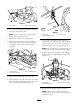
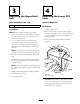
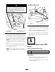


Figure 8
1. Upper PTO lever 3. Lower PTO lever
2. Stop engagement bracket
Figure 9
1. Lower PTO lever
3. Cotter pin (through the
stud)
2. Flange locknut (2)
4. Belt
Note: If the tank w as not remo v ed, remo v e
the plastic film from under the fuel cap and
re place the fuel cap .
2. Install the fuel tank.
3. Slide the dec k under the tractor and connect
the lift links and the front hang er bar as
described in the Operator’ s Manual .
4. Attac h the dec k eng ag ement cable spring to
the right idler brac k et assembly .
5. Install the dec k eng ag ement cable spring to the
right idler brac k et assembly .
6. Install the dec k eng ag ement cable into the rear
cross brace ( Figure 10 ).
Figure 10
1. Hairpin clip 2. Screw and spacer
7. Connect the dec k eng ag ement cable loop end
to the stud on the new lo w er PTO lev er with
the new cotter pin ( Figure 9 ).
Note: No flat w asher is required.
8. Inser t the cotter pin and bend the cotter pin
ends as sho wn in Figure 11 .
Figure 11
9. Place the upper dec k belt around the engine
pulley .
Note: Ensure that the belt is not twisted.
10. Install both engine pulley belt guides ( Figure 1 ).
11. With the dec k installed and lev eled properly ,
raise the dec k to its highest cutting position.
12. Ensure that the belt has sufficient clearance
with the stud on the lo w er PTO lev er when
5