
Installation Instructions


the PTO is in the eng ag ed position, the unit is
r unning, and the dec k is eng ag ed.
Do not get y our hands or feet near the
cutting deck when the engine is r unning .
13. Shut off the engine . If the clearance is g ood
with the dec k r unning in the highest position,
y ou ha v e completed the procedure .
Note: If the lo w er PTO lev er stud still
interferes with the upper dec k belt when
r unning in the highest cutting position, then
g o to the next ste p .
Note: T he follo wing ste p will result in the
cutting dec k cutting lo w er in all positions . T he
lo w est position ma y cause scalping if the dec k
wheels are not properly adjusted.
14. R elease the man ual PTO lev er in the
diseng ag ed position and lo w er the dec k to its
lo w est cutting height.
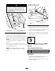
15. F rom the right or left side of the tractor , locate
the rear dec k lift ar m ( Figure 12 ).
Figure 12
1. Deck lift bracket
4. J-pin
2. Lift arm 5. Move the lift cable pin here.
3. Lift cable clevis pin
16. Suppor t the dec k so that there is no w eight
hanging on the lift ar m.
17. Pull the J-pin out so that the lift ar m diseng ag es
from the dec k lift brac k et.
18. R emo v e the cotter pin and clevis pin that
secures the lift cable to the lift ar m ( Figure 12 ).
19. R emo v e the clevis pin and mo v e the lift cable
end loop to the hole indicated in Figure 12 .
Secure the lift cable with the clevis pin and
cotter pin previously remo v ed.
20. R e peat ste ps 16 through 19 for the other lift
ar m.
21. Raise the dec k to its highest cutting position.
22. Ensure that the belt has sufficient clearance
with the stud on the lo w er PTO lev er when
the PTO is in the eng ag ed position. Chec k
this clearance when the unit is r unning and the
dec k eng ag ed.
Do not get y our hands or feet near the
cutting deck when the engine is r unning .
6