
Installation Instructions

All Rights Reserved
Printed in the USA
1
W 2002 by The Toro Company
8111 Lyndale Avenue South
Bloomington, MN 55420-1196
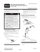
Bio–Diesel Fuel Filter Kit
Greensmaster
)
3250–D Traction Unit
Part No. 112–9182
Form No. 3357–677 Rev. B
Installation Instructions
Note: This kit is intended for use on traction units with
serial numbers prior to 270000001. Also, on machines with
serial numbers 260000001 and up, the fuel hoses do not
need to be replaced.
Danger
Under certain conditions, diesel fuel and fuel
vapors are highly flammable and explosive. A fire
or explosion from fuel can burn you and others
and can cause property damage.
• Use a funnel and fill the fuel tank outdoors, in
an open area, when the engine is off and is cold.
Wipe up any fuel that spills.
• Do not fill the fuel tank completely full. Add fuel
to the fuel tank until the level is 1/4 to 1/2 in. (6
to 13 mm) below the bottom of the filler neck.
This empty space in the tank allows the fuel to
expand.
• Never smoke when handling fuel, and stay away
from an open flame or where fuel fumes may be
ignited by a spark.
• Store fuel in a clean, safety-approved container
and keep the cap in place.
Draining the Fuel Tank
1. Park the machine on a level surface, lower the cutting
units, stop the engine, engage the parking brake and
remove the key from the ignition switch.
Note: If the hoses are not going to be replaced, simply
close the fuel shut off valve and proceed to Replace the
Fuel Separator.
2. Drain the fuel tank as follows:
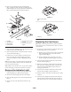
A. Close the fuel shut off valve below the fuel tank
(Fig. 1).
1
Figure 1
1. Fuel shut-off valve
B. Disconnect the fuel hose (Item 2, Fig. 2) from the
fuel separator inlet (Fig. 2). Place the hose into a
suitable container which will also be used when
draining the tank.
C. Drain the fuel tank completely by opening the fuel
shut off valve.
Replace the Fuel Separator
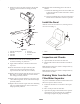
1. Loosen the hose clamps securing the fuel hoses to the
fuel separator (Fig. 2).
2. Unplug the harness connector from the fuel separator.
1
3
4
2
Figure 2
1. Fuel separator
2. Fuel hose
3. Fuel hose
4. Frame mounting bracket
3. Remove the (2) screws securing the fuel separator to the
frame bracket (Fig. 2) Remove and discard the fuel
separator.