Form No. 3440-971 Rev A Electrical Accessory Kit Groundsmaster® 360 Multi-Purpose Machine Model No. 115-0019 Installation Instructions Installation Loose Parts Use the chart below to verify that all parts have been shipped. Procedure 1 2 3 4 5 6 7 8 © 2021—The Toro® Company 8111 Lyndale Avenue South Bloomington, MN 55420 Description Use Qty. No parts required – Prepare to install the hydraulic and electrical mounting kit. No parts required – Disconnect the battery.
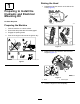
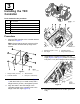
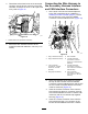
Raising the Hood 1 1. Release the latches at each of the side of the hood (Figure 2). Preparing to Install the Hydraulic and Electrical Mounting Kit No Parts Required g185794 Preparing the Machine 1. Park the machine on a level surface. 2. Ensure that the power take-off is disengaged. 3. Engage the parking brake. 4. Shut off the engine and remove the ignition key. g185793 Figure 2 2. Raise the hood and secure it with the hood support (Figure 3). g038682 Figure 1 g038671 Figure 3 1.
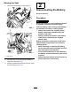
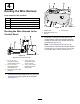
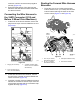
Raising the Seat 1. 2 Tilt forward the steering column (Figure 4). Disconnecting the Battery No Parts Required Procedure WARNING Electrical sparks can cause the battery gasses to explode, resulting in personal injury. Incorrect battery cable routing could damage the machine and cables, causing sparks. g038673 • Always disconnect the negative (black) battery cable before disconnecting the positive (red) cable.
g186714 g038680 g038679 g186715 Figure 6 Machines with Yanmar Engines Figure 5 Machines with Kubota Engines 1. Positive battery post 2. Positive battery terminal 3. Negative battery post 1. Positive battery terminal 3. Negative battery post 4. Negative battery terminal 2. Insulated cover 4. Negative battery terminal 4 1. Disconnect the negative (black—ground) cable from the battery post (Figure 5 or Figure 6). 2.
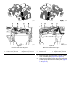
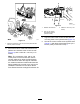
3 Installing the TEC Controller Parts needed for this procedure: 1 TEC Controller 1 Controller bracket 4 Bolt (1/4 x 1-3/8 inches) 4 Flange locknut (1/4 inch) 2 Carriage bolt (3/8 x 1 inch) 2 Flange locknut (3/8 inch) g038677 Procedure 1. Align the TEC controller to the controller bracket as shown in Figure 7. Note: Ensure that the 50-pin connector of the TEC controller is toward the top edge of the bracket. g038676 Figure 8 1. Carriage bolt (3/8 x 1 inch) 3. Controller bracket 2.
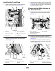
4 Routing the Wire Harness Parts needed for this procedure: 1 Wire harness (mounting kit ) 9 Cable tie—184 mm (7-1/4 inches) 2 Flange-head screws (#10 x 3/4 inch) 2 Flange locknut (#10) 1 Cable tie—368 mm (14-1/2 inches) g038672 Figure 11 1. Hydraulic tank Routing the Wire Harness to the Control Panel 3. Control panel 2. Socket-head screw (1/4 x 5/8 inch) 2.
g038712 Figure 13 1. Platform wire harness 3. Cable tie—184 mm (7-1/4 inches) 2. 198 cm (78 inches) wire-harness branch (control console) 4. Align the holes of the control console with the mounting holes in the hydraulic tank (Figure 11). 5. Secure the control console to the hydraulic tank (Figure 11) with the 6 socket-head screw (1/4 x 5/8 inch) that you removed in step 1. g038670 Figure 12 1. Electrical connectors—198 cm (78 inches) wire-harness branch (control console) 3.
Installing the Fuse Block 1. 3. Route the wire harness of the kit across the bottom of the seat channel (Figure 14). Assemble the fuse block to the mounting tabs (Figure 15) with the 2 flange-head screws (#10 x 3/4 inch) and locknuts (#10), and tighten the screws and nuts by hand. Connecting the Wire Harness to the TEC Controller 1. Route the trunk of the wire harness along the hydraulic hoses of the front traction motors (Figure 16). g038781 g186772 Figure 16 Figure 14 1. Cable ties 2.
4. Connecting the Wire Harness to the Accessory Harness Interface and CAN Interface Connectors Thread the socket-head screw of the 50-socket connector into the 50-pin connector of the TEC controller, and torque to 2.8 to 3.1 N∙m (25 to 28 in-lb); refer to Figure 18. 1. At the trunk of the kit wire harness adjacent to the TEC controller that you installed in 3 Installing the TEC Controller (page 4), remove the cap from the 2-pin connector labeled ACCESSORY HARNESS CAN INTERFACE (Figure 19).
Routing the Forward Wire Harness Branches INTERFACE until the connectors snap together securely (Figure 19). 5. Ensure that the section of the wire harness below the seat will clear the seat bracket when the seat is lowered. 1. Route the 145 cm (57 inches) wire-harness branch and the 43 cm (17 inches) wire-harness branch forward and long the hose for the front traction motors (Figure 21 and Figure 22). Connecting the Wire Harness to the 2-WD Connector (2015 and Before 2-Wheel Drive Machines) 1.
5 Installing the Power Point Receptacle Parts needed for this procedure: 1 Power point receptacle and jam nut 1 Power point bracket 1 Power point cover Procedure g038783 1. Figure 22 1. Front of the machine 3. 43 cm (17 inches) wire-harness branch 2. 145 cm (57 inches) wire-harness branch 2. Route the 43 cm (17 inches) wire-harness branch across the back side of the frame of the machine as shown in Figure 22. 3.
g038684 Figure 25 1. Jam nut 3. Power point receptacle 2. Power point bracket 3. Connect the violet colored wire of the 43 cm (17 inches) wire-harness branch to the positive (+) spade connector of the power point receptacle (Figure 26). g038776 Figure 27 1. Power point bracket 6. 2. Power point cover Align the power point, bracket, and cover to the top of the pivot tube (Figure 28). Note: Ensure that the support clamp is above the power point bracket and cover. g038686 Figure 26 1.
inches) and flange locknut (5/16 inch) that you removed in step 1. 8. Torque the bolt and flange locknut to 1978 to 2542 N∙cm (175 to 225 in-lb). 6 Installing the 179 cm (70-1/2 inch) Wire-Harness Branch (Battery-Cable Lead) Parts needed for this procedure: 5 Cable tie—184 mm (7-1/4 inches) 3 Cable tie—368 mm (14-1/2 inches) g187106 Figure 30 Routing the 179 cm (70-1/2 inch) Wire-Harness Branch (Machines with Kubota Engines) 1. 1. 179 cm (70-1/2 inch) branch (kit wire-harness) 3.
g187122 g187109 Figure 33 5. Route the 179 cm (70-1/2 inch) wire-harness branch along the positive battery cable as shown in Figure 34. g187108 Figure 32 4. Route the 179 cm (70-1/2 inch) wire-harness branch forward, along the wire harness of the machine as shown in Figure 33. g187110 Figure 34 6.
Important: Ensure that the wiring harness is routed away from cylinder located above the battery, as this part moves when rear wheels are turning. 7. Secure the 179 cm (70-1/2 inch) wire-harness branch to the wire harness of the machine with 4 cable ties as shown in Figure 30, Figure 31, Figure 32, and Figure 33. 8. Assemble the storage-compartment housing that you removed in step 1 onto the 2 shoulder head screws at the seat channel and the top flange of the inner compartment housing (Figure 29).
5. Route the wire harness rearward between the hydraulic tank and the lower ROPS tube (Figure 37). 6. Rotate the power center rearward until it is fully seated (Figure 37). 7. Route the wire harness along the platform harness of the machine as shown in Figure 38. Assembling the Wire Harness to the Positive Battery Cable 1. Remove the battery clamp nut from the T-bolt from the battery-post clamp of the positive battery cable (Figure 39). g186902 g038713 Figure 39 1. T-bolt 2.
7 8 Completing the Installation of the Kit Programming the TEC Controller No Parts Required Parts needed for this procedure: Lowering the Seat 1. Support the seat. 2. Stow the seat support; refer to Figure 4 in Raising the Seat (page 3). 3. Lower the seat until it latches securely; refer to Figure 4 in Raising the Seat (page 3). 2. Secure the battery cable to the post and tighten the T-bolt and battery clamp nut by hand. 3.
Maintenance Replacing the Inline Fuse 1. Replacing the Fuse Raise the hood; refer to Raising the Hood (page 2). Replacing the Fuse at the Fuse Block 1. Raise the seat; refer to Raising the Seat (page 3). 2. Remove the open fuse (Figure 40). g038709 Figure 41 1. Cover 2. Fuse (2 A) g038708 2. Locate the inline fuse block at the right side of the engine along the upper chassis tube (Figure 41). 3. Remove the cover of the inline fuse block (Figure 41). 4.
Notes: