
Installation Instructions
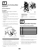
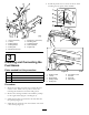

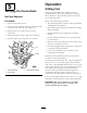
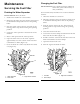


Figure3
1.Locknut(5/16inch)7.Bolt(5/16x1-3/4inches)
2.J-clamp8.Mountingplate
3.Existinglocknut
9.Fuellterbracket
4.Existingwasher10.Waterseparator
5.Existingbolt11.Enginestrap
6.Bolt(5/16x3/4inch)
3
InstallingandConnectingthe
FuelHoses
Partsneededforthisprocedure:
1Hose
3Hoseclamp
1J-clamp
2Plastictie
Procedure
1.Routethefuellterandfuelhosetowardsthefuel
selectorvalve.Makesurenopartsorhosesare
touchingthemachineinareasthatwillgethot.
2.RemovetheexistinghardwareandintalltheJ-clamp
totheengineframe(Figure3andFigure4).
3.Installthefuelhoseconnectedtothefuellterinto
theJ-clamp(Figure4).
4.Installthenewfuelhoseontofuelselectorvalvewith
ahoseclamp(Figure4).
5.Installtheplastictiestosecurethehosesfrom
touchinganyhotpartsofthemachine.
Figure4
1.Existinglocknut6.Fuelselectorvalve
2.J-clamp
7.Fuellter
3.Engineframe
8.Fuelhose
4.Existingwasher9.Hoseclamp
5.Existingbolt
3