
Installation Instructions


FormNo.3362-910RevA
SparkArrestorKit
Kawasaki-PoweredWalk-BehindGreensmasterMowers
ModelNo.117–1441
InstallationInstructions
Installation
1
Formodelswithserial
numberspriorto269999999
NoPartsRequired
Procedure
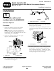
1.Removethemuferguardfromthemufer
bracket(s)(Figure1).Retainthefasteners.
Note:Steps2thru5arenotrequiredunless
thesparkarrestorkitisbeingmountedonany
Greensmaster500oraGreensmasterFlex21witha
serialnumberpriorto220000001.
2.Removethemuferbracketfromtheengine
(Figure1).Retainthefasteners.
G01 1628
1
2
Figure1
1.Muferguard2.Muferbracket
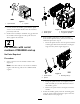
3.Cutoffthedeectorendofthemountingbracketat
thebendasshowninFigure2.
G01 1629
1
2
Figure2
1.Mufermountingbracket2.Cutoffhere
4.Remountthemuferbrackettotheenginewiththe
fastenerspreviouslyremoved.
5.Cutthethreeconnectingtabsallowingtheremoval
oftheknockoutplugintheendofthemuferguard
(Figure3).
G01 1630
1
2
Figure3
1.Connectingtabs
2.Knockoutplug
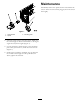
6.Mountthesparkarrestortothemuferguardwith
(4)#10-24x1-1/4inchhex-headscrews,spacer
tubesandlocknuts(Figure4).Assemblethespark
arrestorwiththeexhaustpipedirecteddownwardat
a45degreeangleandawayfromengine.
©2009—TheToro®Company
8111LyndaleAvenueSouth
Bloomington,MN55420
Registeratwww.Toro.com.
OriginalInstructions(EN)
PrintedintheUSA.
AllRightsReserved