
Installation Instructions
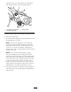

suspensionarm,youmaypositiontheadjustment
boltanywhereintheslotinthespringretainer.
G017713
1
2
Figure2
1.Adjustmentboltlocatedin
thecenteroftheslot
2.Springretainer
5.Repeatsteps3and4fortheother2suspensionarms.
6.Raisethecuttingunits.
7.Ensurethatthecuttingunitsareperpendiculartothe
forwarddirectionoftravel.
Note:Toadjustthealignmentofacuttingunit,
loosenthemountingboltandangenutandthe
adjustmentboltonthesideofthesuspensionarm
necessarytocorrecttheproblem,andalignthe
cuttingunitsothatitisperpendiculartotheforward
directionoftravel.
Note:Ifyoucannotproperlyalignacutting
unitafterinstallingthenewspring-and-retainer
assemblies,dothefollowing:Loosentheadjustment
boltonthesideofthesuspensionarmthatisinthe
centeroftheslotofthespringretainer;loosenand
positiontheadjustmentboltontheothersideof
thearmsothatitisinthecenteroftheslotinthe
springretainer;andalignthecuttingunitsothatitis
perpendiculartotheforwarddirectionoftravel.
8.Foreachsuspensionarm,tightenallmountingbolts
andangenutssecurely,thentightenalladjustment
boltssecurely.
2