
Operator's Manual
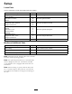
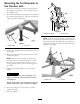
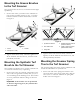
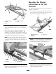

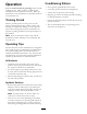

Figure7
1.Springtineholder
4.Retainerbracket
2.Flagpin5.Bolt
3.Bolt
2.Securethespringtineholdertotheturfgroomer
witharetainerbracketand(2)5/16x1inchbolts
(Figure7).
3.Securethetabonthespringtineholdertothe
turfgroomerwiththequickpin(
Figure8).The
attitudeofthespringtinegroomercanbeadjusted
bymovingthelocationofthequickpintoadifferent
setofholesonthemountingtabandgroomer.
Note:Tolockthespringtineholderintoworking
orstoragepositionaslightforceinwardmaybe
requiredtoalignthequickpintothemountingtab
(
Figure8).
Figure8
1.Quickpin
2.Mountingtab
4.Tightenalltheboltsandnutsrmly.Checkthe
tightnessofallthehardwareaftertherstuse,and
checkperiodicallythereafter.
MountingtheMagnet
AttachmenttotheTurf
Groomer
Themagnetattachmentistobetousedonlywiththe
syntheticturfbrushes.
1.Secureeachofthemagnetattachmentbracketsto
thetopoftheturfgroomerwith(2)5/16x1inch
angeboltsandangenuts(
Figure9).
Figure9
1.Magnetattachment
bracket
3.Flangenut
2.Flangebolt
Note:Toeasethemountingoftheattachment
bracketstotheturfgroomer,thetensiononthe
torsionspringsmaybereleased(Figure10).
Figure10
1.Torsionspring
2.Tightenalltheboltsandnutsrmly.Checkthe
tightnessofallthehardwareaftertherstuse,and
checkperiodicallythereafter.
8