Form No. 3365-410 Rev B Beacon Kit Groundsmaster®4000–D/ 4100 Series Traction Unit Model No. 119–8328 Installation Instructions Installation Loose Parts Use the chart below to verify that all parts have been shipped. Procedure 1 2 3 4 5 6 © 2011—The Toro® Company 8111 Lyndale Avenue South Bloomington, MN 55420 Description Use Qty.
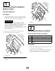
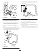
1 Disconnecting the Negative Battery Cable No Parts Required Procedure 1. Position the machine on a level surface, lower the cutting units, stop the engine, engage the parking brake and remove the key from the ignition. Figure 2 CAUTION 1. Battery If you leave the key in the ignition switch, someone could accidently start the engine and seriously injure you or other bystanders. 2 Remove the key from the ignition before you do any maintenance. Installing the Beacon Switch 2.
4. Follow the directions on the template to cut the rectangular hole in the steering tower for the beacon switch (Figure 5). 5. Remove the plug from the switch mounting hole in the back of the steering tower (Figure 5) 6. Install the accessory decal onto the steering tower (Figure 5). 7. Insert the switch into the hole in the steering tower (Figure 5). Figure 3 1. Hydraulic line cover 2.
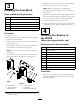
7. Plug the harness connector into the new fuse block. 3 8. Install the 10 amp fuse to the fuse block Note: Make sure the fuse is installed in the corresponding slot that has the wire connected to the harness. Installing the Fuse Block Parts needed for this procedure: 1 Fuse block 2 Screw, #10 X 5/8 Inch 1 Fuse blade 2 Lock nut, #10 1 Decal, beacon 4 Cable tie 9. Affix the fuse decal to the corresponding location on the fuse block decal (Figure 6).
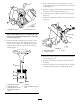
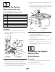
6. Position the beacon mount so it is 15 inches (38 cm) from the top of the ROPS and tighten the U-bolt nuts (Figure 9). Figure 7 1. Cable tie 2. Wire harness Figure 9 3. Lock washer 4. PTO manifold 1. 15 inches (38 cm) 2. Remove one of the screws and nuts securing the PTO manifold to the left frame rail (Figure 7). 7. Mount the beacon socket to the beacon mount with the jam nut included (Figure 8). 3.
4. Route the wire harness to the left upright of the cab ROPS. 5 5. Secure the beacon mount (cab) to the tab on the left rear corner of the cab frame with a 3/8 x 7/8 inch screw and a 3/8 inch flange nut (Figure 11). Installing the Beacon (When equipped with a cab) Parts needed for this procedure: 1 Beacon 1 Beacon socket 1 Beacon mount, cab 1 Screw, 3/8 x 7/8 inch 1 Flange nut, 3/8 inch 1 Lockwasher 4 Cable tie, 14–1/2 inch 2 Cable tie, 5–1/2 inch 2 Mounting pad Figure 11 1. Beacon 2.
Notes: 7