
Installation Instructions


g024885
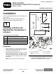
Figure2
1.Straighthydraulictting3.90-degreehydraulictting
2.Deck-lockmanifold
4.Installthestraighthydraulicttingintothetopof
themanifold(Figure2).
5.Installthe90-degreehydraulicttingintothe
endofthemanifold(Figure2).
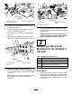
6.Placeadrainpanunderthejunctionmanifold
(Figure3).
7.Disconnectthehydraulichosefromthelower
centerttingonthejunctionmanifold(Figure3).
g335396
Figure3
1.Hydraulichose
3.Junctionmanifold
2.O-ring
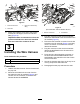
8.Routeandinstalltheendofthehose
disconnectedfromthejunctionmanifoldttingto
thetop(straight)ttingonthedeck-lockmanifold
(Figure4).
Note:MakesurethatallO-ringsareinplace
andlubricatedwithhydraulicuidbefore
installation.
g024887
Figure4
1.Newhose
3.Deck-lockmanifoldtop
tting
2.Disconnectedhose
9.Routeandinstallthenewhosetothejunction
manifoldandthe90-degreedeck-lockmanifold
tting(Figure4).
Important:Makesurethehosefromthe
junctionmanifoldtothedeck-lockmanifold
doesnotcontactthenumber1liftarm.
2
InstallingaDeck-Lock
ManifoldfortheNumber5
LiftArm
Partsneededforthisprocedure:
1
Leftmanifoldassembly(Partno.119-8639)
1
Straighthydraulictting
1
90-degreehydraulictting
2
Selftappingscrew(1/4x1-3/4inch)
1Hydraulichose
Procedure
1.UsingthedimensionsshowninFigure5,locate,
markanddrill2holes(0.221or0.228inch,#1
or#2drillsize)inthetractionunitframetubefor
thenumber5liftarm.Drillthroughonly1wall
ofthetube.
2