
Installation Instructions


g024888
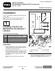
Figure5
1.4.4cm(1.75inches)3.4.1cm(1.63inches)
2.Holes(0.221or0.228
inch)
4.3.5cm(1.38inches)
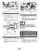
2.Mounttheleftdeck-lockmanifoldtotheframe
tubewith2selftappingscrews(1/4x1-3/4inch).
PositionthemanifoldasshowninFigure6.
g024889
Figure6
1.Straighthydraulictting3.90-degreehydraulictting
2.Deck-lockmanifold
3.Installthestraighthydraulicttingintothetopof
themanifold(Figure6).
4.Installthe90degreehydraulicttingintotheend
ofthemanifold(Figure6).
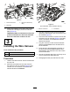
5.Placeadrainpanunderthejunctionmanifold
(Figure7).
6.Disconnectthehydraulichosefromthelower
leftttingonthejunctionmanifold(Figure7).
g336576
Figure7
1.Hydraulichose
3.Hydraulictting
2.O-ring
4.Junctionmanifold
7.Routeandinstalltheendofthehose
disconnectedfromthejunctionmanifoldttingto
thetop(straight)ttingonthedeck-lockmanifold
(Figure8).
Note:MakesurethatallO-ringsareinplace
andlubricatedwithhydraulicuidbefore
installation.
3