
Installation Instructions


g024891
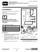
Figure8
1.Disconnectedhose
3.Deck-lockmanifoldtop
tting
2.Newhose
8.Routeandinstallthenewhosetothejunction
manifoldand90-degree,deck-lockmanifold
tting(Figure8).
Important:Makesurethatthehosefromthe
junctionmanifoldtothedeck-lockmanifold
doesnotcontactthenumber5liftarm.
3
InstallingtheWireHarness
Partsneededforthisprocedure:
1Wireharness
4
Cabletie
Procedure
1.Unlatchandraisetheseat.Securetheseatwith
theproprod.
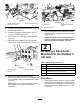
2.Disconnecttheelectricalconnectorfromthe
S5solenoidontheliftmanifold(Figure9)and
connectittotheconnectoronthedeck-lock
harnesslabeledS5HARNESS.
g024892
Figure9
(Groundsmaster4700–DMachineShown)
1.Harnessconnectors
2.Liftmanifold
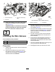
3.Plugtheconnectoronthedeck-lockharness
labeledS5SOLENOIDtotheS5solenoidonthe
liftmanifold(Figure9).
4.DisconnecttheelectricalconnectorfromtheS6
solenoidontheliftmanifold(Figure9)andplug
ittotheconnectoronthedeck-lockharness
labeledS6harness.
5.Plugtheconnectoronthedeck-lockharness
labeledS6SOLENOIDtotheS6solenoidon
theliftmanifold.
6.Routeandplugtheappropriateconnectoron
thedeck-lockharnesslabeledDECK-LOCK
SOLENOIDtothesolenoidontherearofeach
deck-lockmanifold.
7.Securetheharnessawayfromanysharp,hotor
movingcomponentswithcableties.
8.Disengagetheseatpropandlowertheseat.
4