
Installation Instructions

2
InstallingtheBeaconSwitch
Partsneededforthisprocedure:
1Decal,beacon
1
Switch
1Wireharness
Procedure
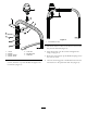
1.Carefullycutandremovethedecalmaterialto
exposetheknockoutinthecontrolpanel(
Figure1).
2.Removetheknockoutfromthecontrolpanelto
exposethenewswitchmountinghole(Figure1).
Filetheedgesoftheholetoremovesharpedges.
1
2
3
G016457
Figure1
1.Beacondecal3.Knockout
2.Switch
3.Cleanthecontrolpanelaroundthemountinghole.
4.Inserttheswitchintothecontrolpanelhole,
positioningasshowninFigure1.
5.Afxthebeacondecaltothecontrolpanel(Figure1).
6.Onmachinesnotequippedwithacab,removethe
(5)buttonheadscrewssecuringthecontrolpanel
tothetankcover.Onmachinesequippedwitha
cab,removethe(2)buttonheadscrewssecuringthe
accesspaneltothesideofthecontrolpanel.
7.Raisethepanelandplugtheenclosedwireharness
connectorontotheswitch.
8.Locatethewireharnessconnectorlabeled
“Accessory”.Plugthewireharnessconnectorinto
theconnector.
9.RoutetheharnesstotherightROPStubeorthe
rightrearcornerofthecab.
10.Cabletietheharnessawayfromanyhotorrotating
componentsandavoidanypossiblepinchpoints.
11.Installthecontrolpaneloraccesspanelwiththe
screwspreviouslyremoved.Torquethescrewsto25
in-lbs(2.8N-m).Donotovertightenthescrews.
3
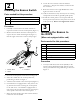
InstallingtheBeaconto
theROPS
(Whennotequippedwithacab)
Partsneededforthisprocedure:
1Beacon
1Beaconsocket
1
Beaconmount,ROPS
1U-bolt
2
Locknut,3/8inch
3Mountingpad
3
Cabletie
Procedure
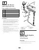
1.Looselyinstallthebeaconmount(ROPS)tothe
insideoftherightROPSuprightwiththeU-bolt
and(2)3/8inchlocknuts,positioningasshownin
Figure2.
2