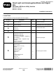
Form No. 3371-324 Rev B Road Light and Homologation/Brake and Signal Kits Workman® MD Series Utility Vehicles Model No. 120-5031 Model No. 120-5044 Installation Instructions Loose Parts Use the chart below to verify that all parts have been shipped. Procedure 1 2 Description Qty. Use No parts required – Prepare the machine. No parts required – Drill the holes for the front signal lights. 3 Brake switch Screw, #6 Locknut, #6 1 2 2 Install the brake switch.
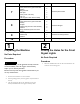
Procedure 7 8 9 10 Description Use Qty. Plate bracket Screw (#10-3/4 inch) (2013 and older models) Wiring harness Plate light Screw (10-24 x 5/8 inch) Lock nut Push clip (2014 and newer models) Light bracket Screw (#10-3/4 inch) (2013 and older models) Tail light Cable-tie clip (2013 and older models) Cable tie Flange-head bolt (2014 and newer models) Rear wiring harness Cable-tie clip Cable tie Lanyard kit 119-9590 (sold separately) 1 1 2 1 2 4 4 5 2 Install the plate bracket.
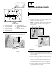
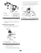
Installing the Brake Switch Parts needed for this procedure: 1 Brake switch 2 Screw, #6 2 Locknut, #6 Procedure 1. Install the brake switch to the pedal assembly using 2 #6 screws and locknuts (Figure 3). Figure 1 Left side shown 1. 12.40 cm (4.88 inch) 5. 4.19 cm (1.65 inch) 2. 5.72 cm (2.25 inch) 6. 7 mm (0.28 inch) diameter hole 7. 4.14 cm (1.63 inch) diameter hole 3. 2.54 cm (1.00 inch) Note: The MDX-D is already equipped with a brake switch.
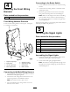
Connecting to the Brake Switch 4 1. Locate the brake switch connector on the front wiring harness. 2. Connect the front wiring harness to the brake switch installed previously. Installing the Front Wiring Harness 3. Route the signal connectors across the front frame along with the existing harness for the head lights.
2. Locate the left, 3–pin connector for the left-signal light on the front wiring harness previously installed. 3. Route the connector under the front fender, and secure the connector to the underside of the fender with the plastic anchor on the harness (Figure 7) Figure 5 1. Clear lamp 4. Shorter bracket leg 2. Amber lamp 5. Hex nut (M5 X 0.88 MM), supplied on light assembly 3. Longer bracket leg 6. Lock washer (M5), supplied on light assembly G017829 Figure 7 1. Plastic anchor 3.
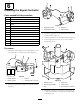
1 6 2 3 4 Installing the Signal Controller Parts needed for this procedure: 1 Column bracket 1 Flasher module 3 Screw (#10-24 x 1/2 inch) 1 Locknut 1 Signal-indicator light 1 Signal-lever switch 1 Hazard switch 2 Speed nut 1 Plug 3. Install the signal lever switch and hazard switch in the column bracket (Figure 9). 1 Column-mount bracket 4. Slide the speed nuts onto the column bracket (Figure 9). 2 Carriage screw 2 Flange nut 1 Column cover G017801 Figure 9 1.
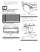
. Connect the wiring harness to the signal-indicator light, signal and hazard switches, and flasher module. 8. Install the column cover with the 2 remaining screws (#10-24 x 1/2 inch) (Figure 10). 7 Installing the Plate Bracket (Model 120-5031 only) G017804 2 1 Parts needed for this procedure: Figure 12 1 Plate bracket 2 Screw (#10-3/4 inch) (2013 and older models) 1 Wiring harness 2 Plate light 3. Insert the wires through the large holes in the plate bracket (Figure 12).
For 2014 and Newer Models 3 2 1 1. Install the plate bracket to the underside of the bed with the 2 existing flange-head bolts (Figure 14). 4 5 G017803 1 2 Figure 14 1. Plate bracket G017809 Figure 15 2. Flange-head bolts 2. Remove the 4 existing wiring harness clips from the wiring harness. 1. Screw (10-24 x 5/8 inch) 4. Wiring harness 2. Plate light 5. Plate bracket 3. Locknut 3. Drill 5 6 mm (1/4 inch) holes as shown in Figure 16. 7. Connect the wires to the 2 plate lights. 4.
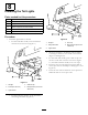
8 Installing the Tail Lights 1 Parts needed for this procedure: 2 Light bracket 4 Screw (#10-3/4 inch) (2013 and older models) 2 Tail light 2 Cable-tie clip (2013 and older models) 2 Cable tie 2 Flange-head bolt (2014 and newer models) 5 3 4 2 G025451 Procedure 1. Install each light bracket to the bed. Figure 18 • For 2013 and older models, secure the brackets with 2 #10-3/4 inch screws (Figure 17). 1. Tail light 4. Push clip 2. Flange-head bolt 5.
4. Route the remainder of the rear wiring harness forward, along the existing main vehicle harness on the right side of the machine (Figure 19). 9 Installing the Rear Wiring Harness 5. Locate the connector on the main vehicle harness labeled Brake and Signal Light Kit, and connect it to the connector on the end of the new wiring harness (Figure 19). Parts needed for this procedure: 6. Secure the wiring harness to the existing main vehicle harness along the frame with a cable tie (Figure 19).
Notes: 11