
Installation Instructions


5
6
7
2
1
3
4
2
g016047
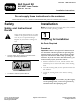
Figure4
1.Rightdeckbeltguard
5.Hexbolt(M6-1X16),
insertedfrombelow
2.Flangenut,existing(2,
onenotshown)
6.Locknut(NIM6-1)
3.Leftdeckbeltguard7.Washer(M6)
4.Self-tappingscrew
(M6-3X19),inserted
fromabove(2)
5.Installthemowingdeckontothetractionunitas
describedintheOperator'sManual.
6.Verifythattheguardsareclearofallmovingparts
acrosstheirfullrangeofoperation,thatitwillnot
causedamagetowires,hosesorothercomponents
andthatitwillnotinterferewiththesafeoperation
ofthetractionunitorthemowingdeck.
3
InstallingtheLeftFrameBelt
Guard
Partsneededforthisprocedure:
1
Leftframebeltguard
4
Hexbolt(M6-1X16)
4
Locknut(NIM6-1)
2
Washer(M6)
Procedure
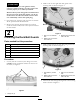
1.AttachtheleftframebeltguardasshowninFigure5.
2
1
3 4
5
6
g016048
7
Figure5
1.Locknut(NIM6-1)(2)5.Hexbolt(M6-1X16),
insertedfrominsideframe
2.Washer(M6)(2)6.Locknut(NIM6-1)
3.Hexbolt(M6-1X16),
insertedfrominsideframe
(2)
7.Openholeinleftframe
beltguard
4.Leftframebeltguard
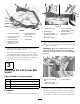
2.Drillaholeintheframejustinfrontoftheleftrear
wheel.Usetheopenholeintheleftframebeltguard
asaguide;seeFigure6.
Important:Thereisabundleofwiresonthe
backsideoftheframewhereyouaredrilling.
Moveitclearofthedrilllocationpriortodrilling
thehole.
Figure6
1.Drilla6.2mmdiameter
hole
3.Locknut(NIM6-1)
2.Hexbolt(M6-1X16),
insertedfrominsideframe
3.InstallthehexboltandlocknutasshowninFigure6.
4.Verifythattheguardsareclearofallmovingparts
acrosstheirfullrangeofoperation,thatitwillnot
causedamagetowires,hosesorothercomponents
3