Form No. 3326-823 Rev A Twister Utility Vehicle Model No. 12003—Serial No.
Warning Stopping the Vehicle . . . . . . . . . . . . . . . . . . . . . . . Parking the Vehicle . . . . . . . . . . . . . . . . . . . . . . . . Cargo Bed . . . . . . . . . . . . . . . . . . . . . . . . . . . . . . . Tailgate Latches . . . . . . . . . . . . . . . . . . . . . . . . . . New Vehicle Break-In . . . . . . . . . . . . . . . . . . . . . Transporting the Vehicle . . . . . . . . . . . . . . . . . . . . Loading the Cargo Box . . . . . . . . . . . . . . . . . . . . Towing the Vehicle . . . . . . . . .
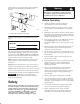
serial numbers of your product ready. Figure 1 illustrates the location of the model and serial numbers on the product. Warning This vehicle is an off-highway vehicle only and is not designed, equipped, or manufactured for use on public streets, roads, or highways. Before Operating • Operate the machine only after reading and understanding the contents of this manual. • Never allow children to operate the vehicle. Anyone who operates the vehicle should have a motor vehicle license.
– Use extra caution when operating the vehicle on wet surfaces, in adverse weather conditions, at higher speeds, or with a full load. Stopping time and distance will increase with a full load. wrong, do not use the vehicle. Make sure that the problem is corrected before the vehicle or attachment is operated. • Since gasoline is highly flammable, handle it carefully. – Avoid sudden stops and starts. Do not go from reverse to forward or forward to reverse without first coming to a complete stop.
• Turning while traveling up or down hills can be dangerous. If you have to turn while on a hill, do it slowly and cautiously. Never make sharp or fast turns. Braking • Slow down before you approach an obstacle. This gives you extra time to stop or turn away. Hitting an obstacle can damage the vehicle and its contents. More important, it can injure you and your passenger. • Heavy loads affect stability.
• Reduce the weight of the load if the center of gravity is high. Items such as bricks, fertilizer, or landscape timbers stack higher in the box. The higher a load is stacked, the more likely the vehicle is to tip over. Distribute the load as low as possible, making sure that the load does not affect rear visibility. Maintenance • Position the weight of the load evenly from side to side. If you position the load toward one of the sides, the vehicle is more likely to tip over while turning.
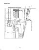
Slope Chart ALIGN THIS EDGE WITH A VERTICAL SURFACE (TREE, BUILDING, FENCEPOST, POLE, ETC.) FOLD ALONG APPROPRIATE LINE. EXAMPLE: COMPARE SLOPE WITH FOLDED EDGE.
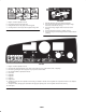
Safety and Instruction Decals Safety decals and instructions are easily visible to the operator and are located near any area of potential danger. Replace any decal that is damaged or lost. 99-7346 1. Parking brake 2. Parking brake on 3. Parking brake off 99-7952 1. Choke 2. Reverse 3. Neutral 4. Forward 99-7350 1. Maximum tongue weight is 50 lb. (23 kg) 99-7349 1. Unlock cargo bed 2. Maximum trailer weight is 400 lb. (181 kg) 2. Lock cargo bed 99-7954 1. Danger—read the operator’s manual. 2.
99-7345 1. 2. 3. 4. 104-6856 Danger—read the operator’s manual. Hot surface hazard—keep hands away. Entanglement hazard—stay away from moving parts. Crushing hazard—use the prop rod to support the cargo bed. 1. Read the operator’s manual for further instructions. 2. The maximum combined operator and passenger weight should not exceed 400 lb. (181 kg). 3. The maximum cargo weight should not exceed 1000 lb. (454 kg). 4. The base weight of the vehicle is 1000 lb. (454 kg). 5.
99-7344 1. Danger—read the operator’s manual. 2. Fuel is flammable. Stop the engine before adding fuel. 3. Tipping hazard—do not drive across slopes that are greater than 15 degrees or up slopes greater than 12 degrees. Reduce speed when turning, carrying heavy loads, or driving on rough terrain. Keep the engine speed under 16 MPH (26 km/h). 4. Passengers are at risk of falling from the vehicle. Do not carry passengers in the cargo bed. Keep arms and legs inside of the vehicle at all times.
Optional Equipment Heavy Duty Bumper Model No. 19050 Camouflage Box Cover Model No. 19060 Brush Guard/Bumper Model No. 19051 Camouflage Full Cover Model No. 19059 Operator Shield Guard Model No. 19052 Camouflage Seat Cover Model No. 19058 Electric Winch Model No. 19053 Camouflage Glove Box and Trash Bag Horn Kit Model No. 19056 Electric Box Lift Heavy Duty Hitch Model No. 07259R Model No. 07275 Part No. 104-6663 ROPS/Seat Belt Kit Model No. 07276R Vinyl Enclosure (Soft Cab) Model No.
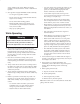
Checking the Crankcase Oil Fuel Tank The engine is shipped with oil in the crankcase; however, the level of the oil must be checked before and after the engine is first started. Recommended Gasoline Use fresh, clean, unleaded regular gasoline suitable for automotive use (87 pump octane minimum). Leaded gasoline may be used if unleaded regular is not available. 1. Position the machine on a level surface. 2. Clean around the oil dipstick (Fig. 2) so dirt cannot fall into the hole and damage the engine.
Filling the Fuel Tank Checking the Transmission Oil The fuel tank capacity is approximately 7 gallons (26.5 l). The transaxle fluid level should be at the bottom of the level indicator hole (Fig. 4). If it is not, fill the reservoir with the appropriate fluid; refer to Changing the Transaxle Fluid, page 28, steps 3 and 4. 1. Shut the engine off and set the parking brake. 2. Clean the area around the fuel tank cap (Fig. 3). 1 1 m–4849 Figure 4 Figure 3 1. Level indicator hole 1. Fuel tank cap 3.
Brake Pedal The brake pedal is used to stop or slow the vehicle (Fig. 5). Caution 1 Brakes can become worn or can be misadjusted resulting in personal injury. If brake pedal travels to within 1 in. (25 mm) of the vehicle floor board, the brakes must be adjusted or repaired. 2 m–5371 3 Figure 6 1. Choke 2. Gear shift selector 2 Gear Shift Selector The gear shift selector has three positions: forward, reverse, and neutral (Fig. 6). The gear shift selector must be in neutral to start the engine.
Light Switch Passenger Hand Holds Toggle the switch to activate the headlights. Push to turn the lights on (Fig. 7). The passenger hand holds are located on the right side of the dash panel and at the outside of each seat (Fig. 9). 2 1 Power Point The power point is used to power 12 volt, optional electrical accessories (Fig. 7). 3 4 m–4887 Figure 9 1. Passenger hand hold 2 1 5 Pre-Starting Checks m–4885 Safe operation begins before taking the vehicle out for a day’s work.
Starting the Engine Cargo Bed 1. Sit in the operator’s seat. Raising the Bed 2. Put the gear shift selector in Neutral. 1. Slide the latch upward toward the top of the cutout in the bed frame (Fig. 10). Note: The engine will only start in Neutral. 2. Lift up on the latch with one hand while raising the bed with the other hand. 3. Insert the key into the ignition switch, turn it clockwise to the Start position, and pull the choke out. When the engine starts, release the key.
Tailgate Latches Transporting the Vehicle 1. To open the tailgate latches, lift the latch handles up (Fig. 12). The latches will spring out toward the center of the tailgate. Slowly lower the tailgate. For moving the vehicle long distances, a trailer should be used. Make sure that the vehicle is secured to the trailer. Refer to Figures 13 and 14 for the location of tie-down points.
Loading the Cargo Box The capacity of the cargo box is 13 ft.3 (0.37 m3). The amount (volume) of material that can be placed in the box without exceeding the vehicle load ratings can vary greatly depending on the density of the material. For example, a level box of wet sand weighs 1500 lb. (680 kg), which exceeds the load rating by 500 lb. (227 kg). But a level box of wood weighs 650 lb. (295 kg), which is under the load rating.
Maintenance Note: Determine the left and right sides of the machine from the normal operating position. Recommended Maintenance Schedule Maintenance Service Interval After first 8 hours Every 8 hours After first 20 hours Maintenance Procedure • Change the engine oil. • Check the drive belt tension. • Check the engine oil. • Check the tire pressure. • Check the front wheel toe-in at the proper ride height. Every 50 hours • Check the battery fluid level. • Check the battery cable connections.
Warning The bed must be raised to perform some routine maintenance. The bed could fall and injure persons that are underneath it. • Always use prop rod to hold bed up before working under raised bed. • Remove any load material from bed before working under raised bed. 1 Figure 15 Heavy Duty Operation 1. Front jacking point Important If vehicle is subjected to conditions listed below, maintenance should be performed twice as frequently.
6. Torque the second locknut to 8–10 in.-lb. (1 N⋅m). Checking the Oil Level 7. Start the engine and shift into Forward, Reverse, and Neutral several times to ensure that the neutral bracket is operating properly. To check the oil level, refer to Checking the Crankcase Oil, page 13. Changing and Draining the Oil 1. Start the vehicle and let it run for a few minutes to warm the oil. 2 2. Park the machine on a level surface, set the parking brake, turn the ignition off, and remove the key. 1 3.
5. Start and run the engine to check for leaks. 6. Stop the engine and recheck the oil level. Add oil if necessary. Cleaning the Engine Cooling Areas ÎÎÎ ÎÎÎ 3 Clean the rotating screen, cooling fins, and external surfaces of the engine every 100 hours of operation or more often under extremely dusty and dirty conditions. Important Operating the engine with a blocked rotating screen, dirty or plugged cooling fins or cooling shrouds removed, will cause engine damage due to overheating.
Installing the Filter Element Important To prevent engine damage, always operate the engine with the complete air cleaner assembly installed. 1. Inspect the new filter for shipping damage. Check the sealing end of the filter. Important Do not install a damaged filter. 2. Insert the new filter properly into the air cleaner body. Ensure that the filter is sealed properly by applying pressure to the outer rim of the filter when installing it. Do not press on the flexible center of the filter. m–5324 3.
• Measure the ride height with the wheels facing straight ahead and a 175–225 lb. (79–102 kg) operator in the driver’s seat. 1. Turn the ignition off and remove the key. 2. Raise the vehicle off of the ground; see Jacking the Vehicle, page 21. Note: The driver should drive up to the measurement area and stay seated in the vehicle while the measurement is being taken. 3. Tighten the cable adjusting screw, located beneath the floor panel, until the cables are snug in the brake equalizer (Fig. 23).
If the vehicle will be run with medium to heavy loads most of the time, set the toe-in on the high side of the recommended amount. If it is going to be run with a light load most of the time, set the toe-in on the low side of the recommended amount. Each hole equals about 3/4 in. (19 mm) of adjustment at the wheel. You will also need to do this if you are adding heavy attachments or carrying heavy loads often. 1.
Servicing the Fuel System 4. Rotate both tie rods to move the front of the tire inward or outward. Fuel Lines and Connections 5. Tighten the tie rod jam nuts when the adjustment is correct. Check lines and connections every 400 hours or yearly, whichever occurs first. Inspect for deterioration, damage, or loose connections. 6. Ensure that there is full travel of the steering wheel in both directions.
3. Check the condition of the side electrode, center electrode, and center electrode insulator to ensure that there is no damage. 3. Fill the reservoir (Fig. 32) with approximately 1-1/2 qt. (1.4 liters) of SAE 10W30 motor oil or until the oil level is at the bottom of the level indicator hole (Fig. 31). 0.030 in. (0.76 mm) 1 Figure 30 Important A cracked, fouled, dirty or malfunctioning spark plug must be replaced.
Replacing the Headlight Bulbs Removing the Battery Replacement bulb: GE #862 1. Position the vehicle on a level surface, set the parking brake, turn the ignition off, and remove key. 1. Set the parking brake, turn the ignition off, and remove the key. Switch the headlights off. 2. Raise the bed and secure with the prop rod. 3. Unhook the battery strap. 2. Reach beneath the dash and rotate the lamp assembly 1/4 turn counterclockwise (Fig. 34). Pull the lamp assembly out of the reflector. 4.
Important Always keep the battery strap in place to protect and secure the battery. Warning Charging the battery produces gasses that can explode. Checking the Electrolyte Level Check the electrolyte level every 50 operating hours or, if the machine is in storage, every 30 days. Never smoke near the battery and keep sparks and flames away from battery. 1. Raise the bed and secure with the prop rod. 3. Install the battery in the chassis; refer to Installing the Battery, page 29. 2.
(–) (+) W/BU LOW OIL PRESSURE 2 5 OR 31 P3–3 P3–1 F7 BK ENGINE OIL PRESSURE HEADLIGHTS LIGHT SWITCH 6 4 3 1 W/BU F6 Y A –M FUEL SOL.
The Toro Total Coverage Guarantee Consumer Vehicles A One-Year Limited Warranty Conditions and Products Covered Items and Conditions Not Covered The Toro Company and its affiliate, Toro Warranty Company, pursuant to an agreement between them, jointly promise to repair any Toro Product used for residential or commercial use if defective in materials or workmanship for a period of one year from the date of purchase.