
Installation Instructions
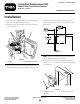
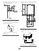
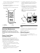


10.Connectthenewwireharnesstotherelays,existing
wireharnessandtothenewreceiver(Figure8).
G018433
1
Figure8
1.Newwireharness
11.Storethenewtransmitteronthetransmittermount
whenitisnotinuse.
12.Connectthepositivebatterycablerstandthen
connectthenegativebatterycable.
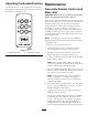
13.Thehandheldandbaseunitshouldbeassociated.
Ifnot,refertoAssociateRemoteControlandBase
UnitintheMaintenanceSection.
Operation
Controls
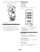
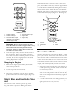
EngineStop
PresstheEngineStopbuttontostoptheengine
(Figure9).
g017705
1 2
3
4
5 6
Figure9
1.Rotatenozzleleft
4.Increasebloweroutput
2.Rotatenozzleright5.Enginestart
3.Decreasebloweroutput
(Pressing3and4together
returnsenginetoidle
6.Enginestop
EngineStart
Aftercompletingthestartingsequence,pressthe
EngineStartbuttontostarttheengine(Figure9).Refer
toStartingtheEngineforthestartingsequence.
NozzleDirection
Presstherightorleftbuttontorotatethenozzletothe
desireddirection(Figure9).
EngineSpeed
PresstheFast(rabbit)orSlow(turtle)buttontoincrease
ordecreasethespeedoftheengine(Figure9).
3