
Installation Instructions

FormNo.3379-122RevB
TrailerBrakeKit
Workman
®
HD/HDX/HDX-DSeriesUtilityVehicle
ModelNo.125-0123
InstallationInstructions
LooseParts
Usethechartbelowtoverifythatallpartshavebeenshipped.
Description
Qty.
Use
Brake-controlharness1
Brakecontroller1
Wireharness1
Screw(10-24x7/8inch)
2
Locknut2
Cabletie
1
Installthebrakekit.
InstallingtheBrakeKit
Note:Thetrailerbrakekitdesignedtoworkdirectlywitha
ToroProSweep,butcanbeusedincustomapplications.For
anycustomapplication,itisrecommendedthatastandard
trailerconnector(notprovided)beused.Also,thetrailer
connectormustbegroundedtothevehiclegroundlocated
nearthebattery.
Note:Makesurethemachineisoffandthekeyisremoved.
1.Usingthecontrollerbracketasatemplate,locate,mark,
anddrilltwo3/16inchdiameterholesinthecenter
oftheatpartofthedashtotheleftsideofsteering
wheelasshownin(Figure1).
2.Mountthebrakecontrollertothedashpanelwiththe
2screws(10-24x7/8inch)andlocknutsprovided
(Figure1).
3.Installthewireharnessasfollows:
A.Disconnectthebattery.
B.Plugthewireharnessintothebrake-controller
connector.
C.Plugthe4-terminalconnectorfromthe
brake-controlharnessintothewireharness.
D.Attachthe2-terminalconnector(onegreen,one
black)tothematingopenconnectorfromthe
Workmanvehicle’swireharness.Thisconnector
islocatedunderthedash.
E.Attachtheharnessringterminaltotheground
boltnearthevehiclefuseblock.
F.Plugtheredharnesswireintotheredwireonthe
backofthefuseblock.
G.Routethewireharnessalongsidethemainvehicle
wireharnesstotherearofthevehicle.
H.Securethewireharnesstothevehicleinseveral
placeswithwireties.Keeptheharnessawayfrom
anyhotorrotatingcomponents.
I.Connectthebattery.
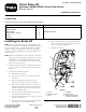
Figure1
1.Locknut
4.Controller
2.Controllerbracket
5.Wireharness
3.Screw
6.Brake-controlharness
(4-terminalconnector)
©2014—TheToro®Company
8111LyndaleAvenueSouth
Bloomington,MN55420
Registeratwww.Toro.com.
OriginalInstructions(EN)
PrintedintheUSA.
AllRightsReserved
*3379-122*B