Form No. 3385-498 Rev A Cargo Bed Installation Kit with Manual Dump or Electric Lift 2011 to 2013 Workman® MD Series Utility Vehicle Model No. 127-7385 Model No. 127-7386 Installation Instructions Safety WARNING CALIFORNIA Proposition 65 Warning This product contains a chemical or chemicals known to the State of California to cause cancer, birth defects, or reproductive harm.
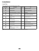
Installation Loose Parts Use the chart below to verify that all parts have been shipped. Procedure 1 2 3 4 5 6 7 8 9 Description Use Qty. No parts required – Prepare the machine. No parts required – Remove the cargo box—machines with a manual cargo-box lift.
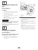
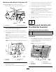
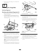
1 Preparing the to Remove the Box 2 3 No Parts Required 1 Procedure 1. Move the machine to a level surface, set the parking brake, turn the ignition off, and remove the key. g014860 2. Completely unload the cargo box. Figure 1 3. Ensure that the tailgate is closed. 1. Latch lever 2. Prop rod 4. Set the new cargo box upside down on the ground next to the machine. Note: Protect the cargo box by placing cardboard or a tarp between the box and the ground. 3. Detent slot 2.
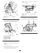
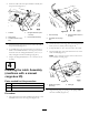
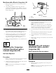
Note: Retain the flanged-head bolts for installation of the new cargo box. Figure 4 1. Flanged-head bolts (3/8 x 1 inch) Figure 2 1. Carriage bolt (5/16 x 5 inch) 3. Serrated nut 2. Saddle bracket 4. Prop rod 3. Rear-frame channel 2. Hinge bracket 9. Lift the latch lever that is at the either side near the forward corner of the cargo box (Figure 1). 10. Lift the cargo box up and off of the machine (Figure 5). 5.
Machines with a Electric Cargo-box Lift 8. Press the lower half of the cargo box lift switch until the cargo-box actuator is fully retracted (Figure 6). Cargo box weight: approximately 57 kg (126 lb) 9. Rotate the key switch to the Off position (Figure 6). 1. Rotate the key switch to the On position (Figure 6). 10. Lower the cargo box onto the chassis. 11. Remove the 4 flanged-head bolts (3/8 x 1 inch) that secure the hinge brackets of the cargo box to the rear-frame channel of the machine (Figure 4).
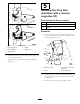
2. Insert the tube end of the pivot-bracket assembly into the pivot block (Figure 9). Figure 9 1. Forward 2. Pivot blocks Figure 10 4. Flanged-head bolts (3/8 x 1-1/2 inch) 1. Latch assembly 3. Flanged head bolt (5/16 x 3/4 inch) 5. Pivot-bracket assembly 2. Threaded inserts (cargo box) 3. Threaded inserts (cargo box) 3. Install the other pivot block over the other tube end of the pivot-bracket (Figure 9). 2.
5 Installing the Prop Rod (machines with a manual cargo-box lift) Parts needed for this procedure: 1 Prop rod 1 Washer (1/2 inch) 1 Hair pin Procedure 1. Insert the long leg of the prop rod through the 12.7 mm (1/2 inch) horizontal hole at the right bottom side of the cargo box (Figure 13). Figure 12 1. Long tang (spring) 4. Spring 2. Latch assembly 5. Spring post 3. Spring saddle 6. Connect the short tang of the spring to the spring post of the latch (Figure 12). 7.
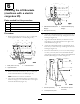
6 Installing the Lift Brackets (machines with a electric cargo-box lift) Parts needed for this procedure: 1 Outboard-lift bracket 1 Inboard-lift bracket 1 Hex-head bolt (5/16 x 5-1/2 inch) 1 Locknut (5/16 inch) Figure 15 1. Outboard-lift bracket (short 3. Inboard-lift bracket (long flanges) flanges) 2. Bolts (5/16 x 3/4 inch) Procedure 4. Attach the outboard-lift bracket to the bed with the 2 bolts that you removed in step1 and tighten the bolts hand tight (Figure 15). 1.
8. Secure the bolt with the flange nut (5/16 inch) hand tight (Figure 16). 7 Installing the Cargo Box No Parts Required Machines with a Manual Cargo-box Lift Figure 18 1. Rotate the cargo box so that the pivot-bracket assembly and prop rod are down. 1. Key hole (prop-rod slot) 2. Using lifting equipment at the front and back of the cargo box, raise the cargo box and align it over the frame of the machine with the pivot-bracket assembly rearward (Figure 17) 2. Prop rod 6.
Machines with a Electric Cargo-box Lift 1. Rotate the new cargo box so that the pivot-bracket assembly is down. 2. Using lifting equipment, lift the cargo box and position it over the frame of the machine so that the pivot-bracket assembly is aligned over the rear-frame channel (Figure 20). Figure 21 1. Latch 3. Latch post 2. Locknut 3. Pull up on the latch lever of the cargo-box latch, push down on the front of the cargo box until it is fully seated, and release the latch lever.
2. Raise the front of the cargo box until the box is approximately at a 45° angle to the chassis of the machine. 3. Rotate the key switch to the On position (Figure 22). Figure 24 Figure 22 1. Lock nut (1/2 inch) 5. Lift-actuator rod 2. 12.7 mm (1/2 inch) hole for the hex-head bolt 6. 12.7 mm (1/2 inch) hole for the clevis pin 4. Press the upper half of the cargo box lift switch until the cargo-box actuator is fully extended (Figure 22). 3. Hex-head bolt (1/2 x 5-1/2 inch) 7.