
Installation Instructions

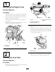


6.Alignthehoseintoanapprovedfuelcontainerwitha
26.5L(7USgallon)capacity(Figure4).
Figure4
1.Fuelhose2.Fuelcontainer
7.Rotatetheshutoffvalveforthefueltankbackand
downtotheOnposition(Figure2).
Note:Allowthefueltanktodraincompletely.
8.Installthehoseandhoseclampontothebarbedtting
atthetopoftheengineswitch(
Figure2).
Note:Ensurethatthebarbedttingisfullyinserted
intotheendofthefuelhoseandthattheclampis
centeredoverthebarbedareaofthetting.
3
RemovingtheFuelTank
NoPartsRequired
Procedure
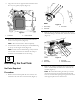
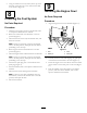
1.Removethehoseclampandtheventhosethatare
attachedtotheventvalveinthefueltank(Figure5).
Figure5
1.Hoseclamp3.Ventvalve
2.Venthose
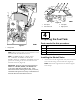
2.Removethehoseclampthatsecuresthefuelhoseto
thebarbedttinginthefuellter,andremovethehose
(Figure6).
Figure6
1.Fuellter
3.Fuelhose
2.Hoseclamp
4.Tank-shutoffvalve
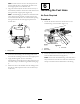
3.Removethe4ange-headboltsthatsecurethefuel
tanktothemachine,andremovethetankfromthe
machine(Figure7).
Note:Becarefulwhenliftingthetankuptoensure
thattheshutoffvalveforthefueltankandthefuel
hosearecenteredwhilepassingthroughtheholeinthe
tank-supportplatefortheshutoffvalve.
3