
Installation Instructions

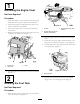
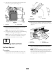
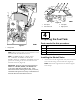

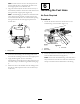

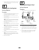

Figure9
1.Fueltank(original)4.Fuelshutoffvalve
2.Coupler5.Fuelhose(original)
3.Fueltank(fuel-tankservice
kit)
6.Fuelhose(fuel-tank
servicekit)
2.Removetheshutoffvalvefromthecouplerinthe
bottomoftheoriginaltank(Figure9).
Note:Discardtheoriginalfueltank.
3.Cleanoffthethreadsoftheshutoffvalve.
4.ApplyPTFEthread-sealingtapetothethreadsofthe
shutoffvalve.
5.Inserttheshutoffvalveintothecouplerofthefuel
tankfromthefuel-tankservicekit,andthreadthevalve
intothecoupler(
Figure9).
6.Tightentheshutoffvalveandpositionthebarbed
ttingtopointtotheleftasviewedfromthebottom
ofthetank(Figure10).
Figure10
1.Forward
4.Fueltankbottom(fuel-tank
servicekit)
2.Fuelhose(fuel-tank
servicekit)
5.Fuel-shutoffvalve
3.Hoseclamp(fuel-tank
servicekit)
7.Positionaclampfromthefuel-tankservicekitover
eachendofthefuelhosefromthekit(Figure9and
Figure10).
8.Installoneendofthefuelhoseoverthebarbedtting
oftheshutoffvalveinthetank(
Figure10).
Note:Ensurethatthebarbedttingisfullyinserted
intotheendofthefuelhoseandthattheclampis
centeredoverthebarbedareaofthetting.
InstallingtheFuelCap
1.Inserttheretainerthatisattheendofthechainfor
thefuelcap/gaugeintothellerneckofthefueltank
(Figure11).
Note:Useascrewdrivertopushtheretainerintothe
cavityofthefueltank.
Figure11
1.Fuelcap/gauge
3.Retainer
2.Chain
4.Fillerneck
2.Alignthefuelcap/gaugeoverthellerneck,andfeed
thechainattheendofthegaugeintothellerneck
(Figure11).
3.Threadthecapontothellerneckofthefueltank
untilitishandtight(Figure11).
5
InstallingtheFuelTank
NoPartsRequired
Procedure
1.Wipethesurfaceofthespacersclean(Figure8).
2.Aligntheslotsinthespacerstothemountingholesfor
thefueltankthatareinthetank–supportplate(Figure
8).
5