
Installation Instructions

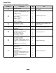

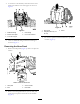
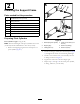


Figure13
1.Cylinderlug(mounting
frame)
3.Bushing(bottomplateof
themountingframe)
2.Gap4.Pivotcylinder(xedend)
3.Determinethenumberofwashers(1x5/16inch)
neededtoreducethegapbetweenthetopofthe
cylindermountingttingandthecylinderlugofthe
mountingframe(Figure13).
Note:Ateachcylinder,usethe(1x5/16inch)
washerstoreducethegapasrequired(0to2washers).
4.Removethecylinderandalignthewasher(s)thatyou
determinedinstep3ontopofthebushinginthe
supportframe(Figure14).
Figure14
1.Cylinderlug(mounting
frame)
4.Washers(1x5/16
inch—useasrequired)
2.Snapring(1-1/8inch)5.Bushing(bottomplateof
themountingframe)
3.Mounttting(pivot
cylinder)
6.Pin(1-1/4x7-5/8inch)
5.Applyacoatofthespeciedgreasetothepin(1-1/4x
7-5/8inch),insidediameteroftheholeinthecylinder
lug,insidediameterofthemountingframebushing,
andinsidediameterofbothmountttingsofthepivot
cylinder(Figure15).
Figure15
6.Alignthemountingttingatthexedendofthe
pivotcylinderbetweenthebushing/washersandthe
mountinglug(Figure14).
Note:AligntheT-ttingtowardthecenterlineofthe
machine.
7.Aligntheholesinthemountinglug,mountingtting,
washer(s),andthebushing(Figure14).
8.Securethecylindertothesupportframewithapin
(1-1/4x7-5/8inch)thatyoupreparedinstep1and
installanapring(1-1/8inch)intotheothergroovein
thepin(Figure14).
9.Repeatsteps2through8fortheotherpivotcylinder.
8