
Installation Instructions

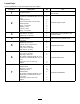


4
ConnectingthePivotCylinder
Hoses
NoPartsRequired
Procedure
1.Removetheplugfromthefreeendoftheleftandright
pivot-cylinderhoses.
2.Connecttheleftpivot-cylinderhosetotheT-ttingat
theleftpivotcylinder(Figure16)andtorquetheswivel
nutofthehoseto21to28N-m(15to21ft-lb).
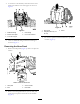
Figure16
1.Pivot-cylinderhose(right)3.T-tting(3/8inch)
2.Pivotcylinders
4.Pivot-cylinderhose(left)
3.Connecttherightpivot-cylinderhosetotheT-tting
attherightpivotcylinder(Figure16)andtorquethe
swivelnutofthehoseto21to28N-m(15to21ft-lb).
4.RotatetheT-ttingsbackandupapproximately60°
(Figure16)andtorquetheswivelnutsfortheT-ttings
to32to39N-m(23to29ft-lb).
5.Removetheshippingplugsfromtheretractportsof
thepivotcylinders.
6.Connectthefreeendofthecross-connecthose(1/4
x20inch)fromtheT-ttingintheleftpivotcylinder
totheretractportoftherightpivotcylinder(Figure
17)andtightenthehosettingattheportto31to39
N-m(23to29ft-lb).
Figure17
1.Cross-connecthose
(T-tting—leftpivot
cylinder)
3.Retractport(leftpivot
cylinder)
2.Retractport(rightpivot
cylinder)
4.Cross-connecthose
(T-tting—rightpivot
cylinder)
7.Connectthefreeendofthehose(1/4x20inch)from
theT-ttingintherightpivotcylindertotheretract
portoftheleftpivotcylinder(Figure17)andtighten
thehosettingattheportto31to39N-m(23to29
ft-lb).
8.Tightentheswivelnutsofbothcross-connecthosesat
theT-ttingsto21to28N-m(15to21ft-lb).
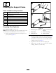
9.Routethecoolantreservoirhosedownandthrough
theholeinthebottomplateofthemountingframe
(Figure18).
Figure18
1.Hole(mountingframe)2.Hose(coolantreservoir)
9