
Installation Instructions

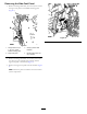
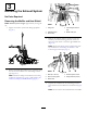
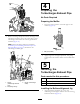
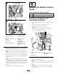
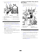
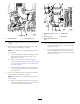
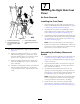

Figure21
1.Exhaust-systemmount
3.Lower-mufersupport
2.Flange-headbolts(1/2
x1inch)—lowermufer
support
4.Serratedangenuts(1/2
inch)
D.Movethemuferleftorrighttoalignthebellows
(Figure21).
E.Tightenthe2ange-headbolts(1/2x1inch)
andserratedangenuts(1/2inch)thatsecure
thelower-mufersupporttotheexhaust-system
mountto91to113N-m(67to83ft-lb).
F.Tightentheange-headbolts(6x30mm)that
securethemuferstrapsto972to1198N-cm
(86to106in-lb).
G.Assembletheheatshieldtoexhaust-systemmount
withthe6ange-headbolts(6x16mm)and
torquetheboltsto972to1198N-cm(86to106
in-lb).
7
InstallingtheRightSideCowl
Panel
NoPartsRequired
InstallingtheCowlPanel
1.Aligntheholesintherightside-cowlpanelwiththe
holesintheROPSplateandtherewall;refertoFigure
5inRemovingtheSide-CowlPanel(page3).
2.AssemblethecowlpaneltotheROPSplatewiththe
ange-headbolt(12x40mm)thatyouremovedin
step1ofRemovingtheSide-CowlPanel(page3).
3.Assembletheclampforthehydraulic-tankbreatherand
side-cowlpaneltotherewallwiththeange-headbolt
(8x35mm)thatyouremovedinstep2inRemoving
theSide-CowlPanel(page3).
Note:Ensurethatthebreatherisverticallyaligned.
4.Tightenthe12mmboltattheROPSplateto80to100
N-cm(59to73ft-lb)andtightenthe10mmboltatthe
rewallto44to57N-cm(34to42ft-lb).
AssemblingtheBattery-Disconnect
Switch
1.Assembletheelectricalcablethatyouremovedinstep
1ofDisconnectingtheBattery-DisconnectSwitch
(page2)ontothreadedstudofthejumppost(Figure
3)withthelocknut.
2.Aligntheelectricalcableatthestudofthejumppost
upward,tightenthelocknut,andaligntheinsulator
bootoverthenutandstud.
3.Assemblethebattery-disconnectswitchintothe
openingatthemountingangeoftherightside-cowl
panel(Figure4)withthelockwasherandjamnutthat
youremovedinstepof3andtightenthejamnut.
Note:Ensurethatthealignmentpinofthedisconnect
switchisalignedwiththeslotinthemountingange
ofthepanelandtheswitchisushtotheange.
4.Installtheknobontotheshaftofthedisconnect
switchwiththescrewthatyouremovedinstep2of
DisconnectingtheBattery-DisconnectSwitch(page2).
10