
Installation Instructions

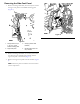
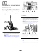
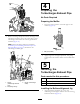
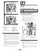
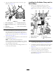
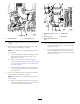
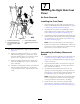

Figure2
1.Positive-batterycable
4.Lock-washernut(3/8inch)
2.Negative-batterycable
5.Negativestud(battery)
3.Ringterminal
6.Positivestud(battery)
6.Movebacktheinsulatorbootandremovethe
lock-washernut(3/8inch)securingthepositive-battery
cabletothepositivestudofthebatteryandremovethe
cablefromthebattery(Figure2).
DisconnectingtheBattery-Disconnect
Switch
1.Attheinboardsideofthejumppost,movebackthe
insulatorboot,removethenut,andremovethecable
formthethreadedstud(Figure3).
Figure3
1.Jumppost
4.Cableterminal
2.Right-cowlpanel5.Insulatorboot
3.Threadedstud6.Locknut
2.Atthebattery-disconnectswitch,removethescrewthat
securestheknobtotheshaftoftheswitch(Figure4).
Figure4
1.Right-cowlpanel4.Jamnut
2.Shaft(battery-disconnect
switch)
5.Knob
3.Lockwasher
6.Screw
3.Removethejamnutandlockwasherthatsecurethe
disconnectswitchtotheright-cowlpanel(Figure4).
4.Pushtheshaftofthebattery-disconnectswitch
rearwardtoseparatetheswitchfromthecowlpanel
(Figure4).
2