
Installation Instructions
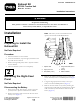

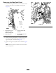
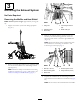
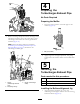
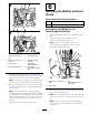
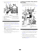
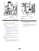
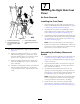

Figure15
1.Turbocharger-exhaust
pipe
5.Pipe-alignmentjig
2.Flange-headbolts(10x
20mm)
6.Standoff(exhaust
manifold)
3.Flangeclamp
7.Smallange
(pipe-alignmentjig)
4.Upper-rearheatshield
8.Pipesurface
(turbocharger-exhaust
pipe)
3.Assemblethepipe-alignmentjigontotheheatshield
andundertheange-headbolts(AofFigure15)and
tightentheboltsto17to21N-m(47to57ft-lb).
Note:Ensurethatthealignmentjigispushedinward
sothattheboltsarefullyseatedintheslotsofthejig.
4.Rotatetheexhaustpipesothatthesurfaceofthepipe
isushtothesmallangeofthepipe-alignmentjig
(BofFigure15).
Note:Thesmallangeofthepipe-alignmentjig
shouldalignbetweenthe2legsofthebellows-alignment
jig.Ifthebracketsarenotaligned,loosentheguillotine
clamp,positionthebellowsjig,andtightentheange
nutsoftheguillotineclampto19to25N-m(14to
18ft-lb).
5.Tightenthenutoftheangeclampsecurely.
6
InstallingtheMuferandHeat
Shield
Partsneededforthisprocedure:
3
Shim1.5mm(0.06inch)
1
Shim0.8mm(0.03inch)
AssemblingtheMufertothe
TurbochargerOutletPipe
1.Alignthebandclamparoundtheturbocharger-exhaust
pipe
2.Aligntheinletpipeofthemuferwiththe
turbocharger-exhaustpipe(Figure16).
Note:Ensurethatthealignmentpinsofthe
muferinletpipearealignedwiththeslotsinthe
turbocharger-exhaustpipeange.
Figure16
1.Alignmentpin(muferinlet
pipe)
3.Slot
(turbocharger-exhaust
pipeange)
2.Bandclamp
3.Inserttheinletpipeintotheexhaustpipeintotheinlet
pipeisfullyseated(Figure16)
Note:Youshouldalignthepinatthemuferinletpipe
nearthebottomoftheslotintheturbocharger-exhaust
pipe.
Note:Donottwistthemuferwhileassemblingit
totheturbocharger-exhaustpipeoryoumaydamage
thebellows.
7