
Installation Instructions
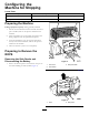
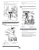

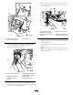

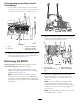
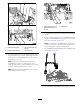


Figure12
1.Flangebolt(8x30mm)
3.Dashassembly
2.Flangelocknut(8mm)
3.Removethepiggybackterminalofthewiringharness
forthemachinefromthebladeterminalofthe
auxiliary-powerport(Figure13).
Figure13
1.Bluewire(dashharness)3.Piggybackterminal(wiring
harnessforthemachine)
2.Socketterminal—black
(ground)wire(dash
harness)
4.Bladeterminal
(auxiliary-powerport)
4.Removethesocketterminalfortheblackwireofthe
dashharnessfromthepiggybackterminalofthewiring
harnessforthemachine(Figure13)
5.Removethe6-socketconnectorofthewiringharness
forthemachinefromtheconnectorforthestarter
switch(Figure14).
Figure14
1.6-pinconnector(wiring
harnessforthemachine)
3.Starter-switchconnector
2.6-socketconnector(dash
harness)
4.6-socketconnector(wiring
harnessforthemachine)
6.Removethe6-pinconnectorofthewiringharnessfor
themachinefromthe6-socketconnectorofthedash
harness(Figure14).
7.Carefullyremovethedashpanelfromtheconsole
(Figure12).
Note:Setasidethedashpanel,angebolts,and
locknutsforassemblyinAssemblingtheMachinefor
Shipping(page9).
5