
Installation Instructions


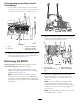


DisconnectingtheAuxiliary-Control
PanelWiring
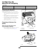
1.Attheauxiliary-controlpanel,removethe10-socket
connectorattheendofthemain-wiringharnessfrom
the10-pinconnectorforthetiltswitch(Figure17).
Figure17
1.Plugs3.Auxiliary-controlpanel
2.Tiltswitch4.10-socketconnectors
(main-wiringharness)
2.Removethe7remaining10-socketconnectorsofthe
main-wiringharnessfromthe7rocker-switchplugsin
theauxiliary-controlpanel(Figure17).
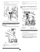
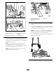
RemovingtheROPS
Lifting-equipmentcapacity:408kg(900lb)minimum
AdditionalEquipment:hand-operatedwinch
1.SupporttheROPSframeandmuferwithlifting
equipmenthavingaminimumliftcapacityof408kg
(900lb)asshowninFigure18.
Note:TheROPSframeandmuferisweighted
towardtherear.YouwillneedtotilttheROPSframe
andmufertoremovetheROPS.Wheneverpossible,
use2piecesofliftingequipmenttolifttheROPSframe
andmufer.
Figure18
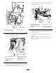
2.Removethe2ange-headbolts(12x40mm)that
securethehoodplate,ROPS-mountingplate,leftcowl
panel,andrightcowlpanel(Figure19)
Figure19
1.Leftcowlpanel3.Hood-plateange
2.Flange-headbolt(12x40
mm)
4.ROPS-mountingplate
3.Removethe2ange-headbolts(16x50mm)
and2angelocknuts(16mm)thatsecurethe
ROPS-mountingplatetotheframeoftheconsole
(Figure20).
Note:Ifyouhavedifcultyremovingthebolts,
theROPSframetubesareundertension.Usea
hand-operatedwinchtopullthefrontROPStube(s)
towardthereartube(s)torelievesheeringpressure
fromthebolts.
Note:Discardthe2ange-headbolts(16x50mm)
and2angelocknuts(16mm).
7