
Installation Instructions


3
RemovingandInstalling
thePivotBracketAssembly
Partsneededforthisprocedure:
2Pivotblock
4
Flanged-headbolt(3/8x1-1/2inches)
Procedure
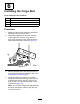
1.Atthenewcargobed,aligntheholesofanew
pivotblocktothethreadedinsertsinthecargo
bed,attachtheblockwiththe2anged-head
bolts(3/8x1-1/2inches)andtightenthebolts
handtight(Figure7).
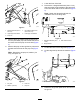
g026340
Figure7
1.Forward
4.Flanged-headbolts(3/8x
1-1/2inches)
2.Pivotblocks5.Pivot-bracketassembly
3.Threadedinserts(cargo
bed)
2.Insertthetubeendofthepivot-bracketassembly
intothepivotblock(Figure7).
3.Installtheotherpivotblockovertheothertube
endofthepivot-bracket(Figure7).
4.Aligntheholesintheblocktothethreaded
insertsinthecargobed,attachtheblockwith
2anged-headbolts(3/8x1-1/2inches)and
tightentheboltshandtight(Figure7).
5.Torquetheanged-headboltsto37to45N∙m
(27to33ft-lb).
4
InstallingtheLatch
Assembly
Partsneededforthisprocedure:
1Latchassembly
4
Flangedheadbolt(5/16x3/4inch)
2Handgrip
Procedure
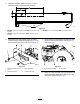
1.Aligntheholesinthelatchassemblyfromthe
kittothethreadedinsertinthenewcargobed
(Figure8).
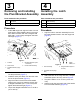
g026338
Figure8
1.Latchassembly
3.Flangedheadbolt(5/16x
3/4inch)
2.Threadedinserts(cargo
bed)
2.Attachthelatchtothecargobedwith4anged
headbolts(5/16x3/4inch);refertoFigure8.
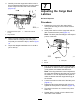
3.Torquetheboltsto15to17N∙m(133to147
in-lb)
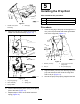
4.Slipthehandgripsontoeachendofthehandle
barofthelatchassembly(Figure9).
4