
Installation Instructions

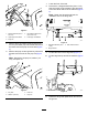

5.UsingthetemplateshowninFigure13,drill2
holes(3/8inch)intotheleftframechannel.
g284410
Figure13
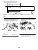
1.MD/MDX—38.18cm(15.03inches);MDE—43.26cm(17.03
inches)
3.MD/MDX—51mm(2inches);MDE—51mm(2inches)
2.MD/MDX—13.46cm(5.30inches);MDE—18.54cm(7.30
inches)
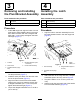
6.Securetheprop-rodbrackettotheleftframe
channelusing2ange-headbolts(3/8x1inch)
and2locknuts(3/8inch)asshowninFigure14.
g284722
Figure14
1.Flange-headbolt(3/8x1
inch)
3.Prop-rodbracket
2.Leftframechannel4.Locknut(3/8inch)
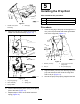
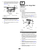
7.Swingtheproprodforwardandinserttheshort
legoftherodthroughthekeyhole(Figure12
andFigure15).
g283640
Figure15
1.Keyhole(proprodslot)
2.Proprod
8.Movethecargobedandproprodrearwarduntil
thepivot-bracketassemblyisalignedoverthe
rearframechannel(Figure15).
7