
Installation Instructions

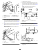
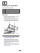

9.Carefullylowerthecargobeduntiltheholesin
thepivotbracketsalignwiththemountingholes
forthecargobedintherearframechannel
(Figure16).
g026345
Figure16
1.Flanged-headbolts(3/8x
1inch)
3.Rearframechannel
2.Hingebracket
10.Attachthepivotbracketstotherearframe
channelwiththe4anged-headbolts(3/8x1
inch)thatyouremovedinstep8;refertoFigure
16.
11.Torquetheanged-headboltsto37to45N∙m
(27to33ft-lb).
7
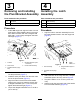
AdjustingtheCargoBed
Latches
NoPartsRequired
Procedure
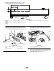
1.Releasetheproprodforthecargobedby
movingtheshortlegoftherodoutoftherear
detentand
2.Gentlylowerthefrontofthecargobeduntilthe
latchcontactsthelatchpost(Figure17).
Note:Thelatchpostshouldaligntotheramped
portionofthelatch.
g002181
Figure17
1.Latch3.Latchpost
2.Locknut
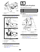
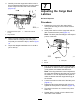
3.Pulluponthelatchleverofthecargobedlatch,
pushdownonthefrontofthecargobeduntilit
isfullyseated,andreleasethelatchlever.
Note:Ifthecargobedlatchisoutofadjustment,
thecargobedvibratesupanddownasyoudrive
themachine.Youcanadjustthelatchpoststo
makethelatchesholdthecargobedsnuglyto
thechassis.
4.Loosenthelocknutontheendofthelatchpost
(Figure17).
5.Rotatethelatchpostclockwiseuntilitissnug
againstthehookportionofthelatch(Figure17).
6.Torquethelocknutto19.7to25.4N∙m(175to
225in-lb).
7.Repeatsteps1through3forthelatchonthe
othersideofthemachine.
8