
Installation Instructions
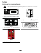


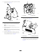

6.RemovetheE-Stopbuttonassemblyfromthecover
(Figure2).
Note:RetaintheE-Stopbuttonassemblyand
correspondinghardwareforlaterinstallation.
g035567
Figure2
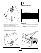
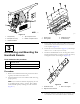
7.Removethe2solenoidconnectorsandthepower
connectorfromtheintermediateharness.
8.Removethewirelessremotebaseunitfromthefender
guard(Figure3).
Important:Onceyouremovethewireless
remotebaseunit,immediatelyinstalltheremoved
hardwarebackontothefenderguard.
g035569
Figure3
2
InstallingtheKit
Partsneededforthisprocedure:
1Rinseguard
2Rivet
1Mountbracket
1
Screw(1/4x5/8inch)
1
Self-tappingscrew(1/4x3/4inch)
1Knobbracket
2
Screw(5/16x3/4inch)
1
Coverassembly
4
Bolt(3/8x3/4inch)
4Hardenedwasher
4Two-piecemount
2
Nut(3/8inch)
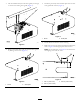
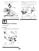
Procedure
1.Removetheboltsandwashersfromthemanifoldblock
andretainthemforlaterinstallation(Figure5).
Note:Donotremovethehydrauliclinesfromthe
manifoldblock.
2.Removetheboltsandnutssecuringtherinseguard
tothemachine(Figure7).
g035687
Figure4
4