
Installation Instructions
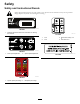


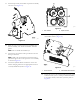

13.InstallthepreviouslyremovedE-stopbuttonassembly
ontothecover(Figure13).
g035757
Figure13
14.Placethecover,withthepreviouslyinstalledE-Stop
buttonassembly,ontothemountbracketandrinse
guard.
Note:Donotinstallthehardwareyet.
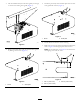
15.ConnectthewireharnessE-Stopconnectionintothe
E-Stopconnection.
Note:MakesurethattheE-Stopconnectionwireis
placedthroughtheslitonthetopofthecoverassembly
asshowninFigure16.
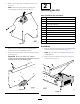
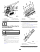
16.Locatethehydraulicblockconnectionsonthewire
harnessandplugthemintotheappropriatelocations
onthehydraulicblock;refertoFigure14.
g035849
Figure14
1.Floorforward2.Optionforward
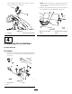
17.Connectthepowerplugconnectorintothe
intermediateharness(Figure15).
g035746
Figure15
1.Powerharness2.Intermediatewireharness
18.Securethecovertothemountbracketandrinseguard
withthe4bolts(3/8x3/4inch),4hardenedwashers,
4two-piecemounts,and2nuts(3/8inch);referto
Figure16.
7