
Installation Instructions


3
InstallingtheWireHarness
Partsneededforthisprocedure:
1Wireharness
1Fusedecal
Procedure
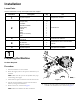
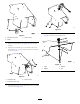
1.LocatetheRF2CANcontrollerendofthewireharness
andplugitintotheRF2CANcontroller(Figure12).
Note:Plugiskeyedandhasaspecicorientation.
g035514
Figure12
1.RF2CANcontroller
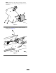
2.Routetheharnessalongtheundersideofthefender
guard.
Note:Placeclipsintheholesdrilledintheunderside
ofthefenderguardtohelpinstalltheharness.
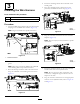
3.RoutetheE-Stopconnectionendofthewireharness
alongtheundersideofthefenderguardasshownin
Figure13.
g035422
Figure13
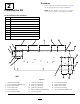
4.Routetheremainingharnessdownthebackofthe
fenderguard.
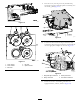
5.PlugtheCANdiagnosticsconnectionintothe
previouslyinstalledwire-harnesscap(Figure14).
g035423
Figure14
6.Plugthecontrollerconnectionsintothecontroller
adapters(Figure15).
Note:Plugsarekeyed,colored,andhaveaspecic
orientation.
g035424
Figure15
7.Routetheremainingharnessonthetopoftheleft
fenderandinfrontofthehydraulicblock.
Note:DonotplugtheE-Stopconnection,relay
connection,ordiagnosticlightconnectionintoan
adapteratthistime.
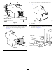
8.Plugthe5harnessconnectionsintotheappropriate
locationsonthehydraulicblock;refertoFigure16
andFigure17.
8