
Installation Instructions


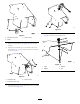

g035425
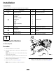
Figure16
g035543
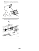
Figure17
1.Floorreverse4.Binraise
2.Floorforward5.Optionforward
3.Binlower
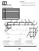
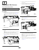
9.Placethecover,withthepreviouslyinstalledrelay,
fuse-blockcap,light,andE-Stopbuttonassembly,onto
thefenderguard(Figure18).
g035516
Figure18
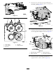
10.ConnectthewireharnessE-Stopconnection,relay
connection,diagnosticlightconnection,andfuseblock
intotheappropriateadaptersasshowninFigure19.
g035433
Figure19
1.Diagnosticlightconnection
3.E-Stopconnection
2.Relayconnection4.Fuseblockconnection
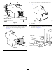
11.Securethecovertothefenderguardwiththe
appropriatebolts,washers,andnuts(Figure20).
9