
Parts Catalogue

2
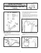
5. Route the loom along the upper portion of the
windshield and down along the left-side ROPS
tube. Loosely secure using cable ties. See Fig. 4.
Fig. 4
UTV-227A
6. Route the wiper motor wires on the left side of the
dash and route to the switch panel in the dash.
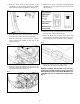
7. With the hood open, remove the two machine
screws securing the middle of the dash to the
frame. See Fig. 5
Fig. 5
UTV-243A
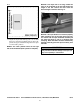
8. Route Accessory Wire-Jumper (23 5/8-in.) into the
accessory plug located under the dash next to the
key switch connection. See Fig. 6.
Fig. 6
UTV-225A
9. Route the accessory wire-jumper through the dash
and plug it into the upper left switch connection
(#4). See Fig. 7.
Fig. 7
UTV-252
10. Route the red wire through the dash and plug it into
the lower left switch connection (#3).
11. Route the black wire from the wiper motor and
secure between the dash and the frame using one of
the self-tapping screws removed in step 7. See Fig.
8.
Fig. 8
UTV-229A
12. Press the switch into the dash until it is fully
seated; then test the function of the wiper.
NOTE: If existing switch mount is full, use tem-
plate below to install the switch to the right of the
existing switch mount. Panel Switch Mount Kit (p/n
1436-008) can also be ordered and installed. See
Fig. 9.