
Parts Catalogue


3
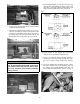
11. Secure Coolant Pump (A) to the storage box using
two self-tapping screws (shown below); then drill a
1-in. hole (B) into the storage box (operator’s side)
directly across from the intake hose barb and
secure coolant hose (3/8-in.) through drilled hole.
See Fig. 8.
Fig. 8
UTV-055A
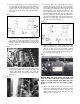
12. Locate the upper radiator hose (operator’s side)
and make a mark approximately seven inches
below the upper bend; then place two suitable hose
clamping devices on either side (A) and cut the
hose (B). See Fig. 9.
Fig. 9
UTV-133A
13. Install Radiator Hose Wye with the branch fitting
towards the heater unit and secure with two
clamps; then install the radiator hose (from the
coolant pump) to the wye and secure with a clamp.
See Fig. 10.
Fig. 10
UTV-125
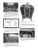
14. Locate and attach two Formed Hoses as shown
with the Fill Tee (A) and secure with two clamps;
then insert the Reducing Coupling (C) into the lon-
gest 90 degree Formed Hose (D), opposite the fill
tee and attach to 5.00” piece of 3/8” ID hose on the
pump’s discharge side. Insert the 3/4” x 3/4” cou-
pling (E) into the 20.00” piece of 3/4” radiator hose
that was pushed into the tub from the radiator tee
previously installed in the lower radiator hose; then
attach to the formed hose coming from the return
(B) port on the heater. See Fig. 11.
Fig. 11
UTV-055B
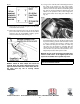
15. Drill two holes on top of the dash panel in the
desired location using a two inch hole saw; then
pull the 2 inch vent hose (previously routed)
through the dash panel and secure with cable ties
(14 in.). Press both vents into the dash making sure
they are fully seated. See Fig. 12.
Fig. 12
ROV-317A
NOTE: Make sure when drilling the upper dash
panel vent holes to not interfere with the shifter (on
HDX) or any main harness wires. Make sure vent
hoses are routed away from all steering compo-
nents.
16. Secure “Y” Fitting to the center vent hose; then
connect two adequate lengths of vent hose to each
other end of the fitting and route to the other two
desired locations of the round vents. Secure using
cable ties (14 in.) See Fig. 13.