
Parts Catalogue


4
Fig. 13
ROV-315A
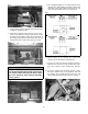
17. On models without a floor console, drill two holes
in the splash panel using a two inch hole saw for
the operator’s/passenger’s vents according to the
illustration below; then pull the 2 inch vent hose
from the “Y” fitting and secure to vents with cable
ties (14 in.). Press vents in making sure they are
fully seated. See Fig. 14.
Fig. 14
UTV-057A
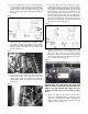
18. On models with a floor console, remove the seats,
console, and floor console. Retain all hardware.
19. Using a two-inch hole saw, drill a hole on both
sides of the floor console; then press in both round
vents. See Fig. 15.
Fig. 15
UTV-119
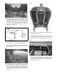
20. Cut the front screen in the floor console to allow
the vent hose and “Y” fitting to access round vents;
then secure vent hoses (from the “Y” fitting) to the
round vents using two cable ties (14 in.). Cable tie
the “Y” fitting to the front screen using cable ties.
See Fig. 16.
Fig. 16
ROV-318
21. Install floor console using existing hardware; then
install console and seats.
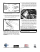
22. Locate black ground wire from the heater and the
coolant pump; then route to the dash support area
and secure using a Self-Tapping Screw. See Fig.
17.
Fig. 17
UTV-130A
23. Route heater wires (yellow and orange) between
tub wall and splash panel; then remove switch
panel below the defroster vent and insert Switch.
Attach the yellow and orange fan speed wires as
shown. See Fig. 18.