
Operator's Manual

NOTE: Read these Installation Instructions thoroughly before beginning the installation process. Retain
these Installation Instructions for future reference.
1
Arctic Cat
®
Prowler
Installation Instructions - Accessory Kit
REV: 1/31/13 Form No. 0453-828
LXC HDX Rear Panel Kit
(p/n 1436-595)
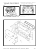
Kit includes:
p/n QTY DESCRIPTION
0541-063 1 Upper Panel (1)
0541-064 1 Lower Panel (2)
0541-067 1 Left-Side Lower Panel (3)
0541-066 1 Right-Side Lower Panel (4)
0541-068 2 Rubber Boot (5)
0541-065 1 Sliding Window Assembly (6)
2441-241 2 C-Clamp (7)
* 11 Button-Head Screw (M6 x 16 mm) (8)
* 2 Button-Head Screw (M6 x 20 mm) (9)
* 4 Nylon Lock Nut (M6) (10)
* 13 Rubber Washer (11)
* 13 Fender Washer (12)
** 1 Upper Foam Seal (13)
** 1 Rear Panel Trim (14)
** 2 Side Panel Foam (15)
** 1 Lower Panel Foam (16)
** 1 Seat Belt Trim (17)
0453-828 1 Instruction
* Included in Hardware Kit (p/n 0541-062)
** Included in Foam/Seal Kit (p/n 0541-069)
Parts illustration on page 2
NOTE: If LXC doors are not being used, side
restraints must be installed and lower side panels
# 3 and #4 from this kit do not need to be installed.
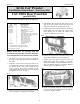
1. Lift up the cargo box; then remove and retain the
four cap screws securing the backrest assembly to
the frame.
2. Slide Rear Lower Panel on the front side of the
rear ROPS tubes and between the backrest assem-
bly and the frame; then loosely install the cap
screws securing the backrest assembly to the
frame making sure the top two screws are installed
through the rear panel. See Fig. 1.
Fig. 1
UTV-187
3. Remove and retain the two torx-head screws and
nuts securing the rear taillight to the ROPS.
4. Slide Rubber Boot around the tube and place the
edge of the lower panel between the lips of the
rubber boot with the slit positioned at the top.
5. Position Upper Panel onto the back side of the rear
ROPS tubes and on the front side of the lower
panel making sure to install the rubber boots
between the both panels. See Fig. 2.
Fig. 2
UTV-171A
6. Position the upper panel so the holes in the panel
align with the holes that secure the taillight.
7. Loosely secure the upper rear panel to the rear
ROPS tubes using two C-Clamps, two Button-
Head Screws (M6 x 20 mm) (installed on the out-
side), two Rubber Washers, two Fender Washers,
and two Nylon Lock Nuts. See Fig. 3.
Fig. 3
UTV-173A
8. Install the taillight using the existing torx-head
screws and nuts; then tighten the screws and nuts
from step 6. Tighten securely.