
Installation Instructions
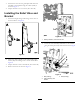

3.InstalltheU-nutsontotheguardplateandsecurethe
assemblytothemachineusingthe2bolts(M10)as
showninFigure1.
4.Torquetheboltsto47to57N-m(34to42ft-lb).
InstallingtheReliefValveand
Bracket
1.InstallthestraightttingsandO-ringstothevalveas
showninBoxAofFigure2.
Figure2
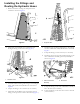
2.Securethevalveassemblytothevalvebracketusing
2bolts(M6)and2angenutsasshowninBoxBof
Figure2.
3.Torquetheboltsto972to1198N-cm(86to106in-lb).
4.Removethe2nutsasshowninFigure3.
Figure3
1.Existinghardware;removethesenuts
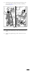
5.Securethevalveassemblyandbrackettothemachine
usingthe2nutspreviouslyremovedasshowninFigure
4.
Figure4
1.Bolt(existing)3.Nuts(existing)
2.Valveassemblyand
bracket
2