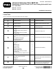
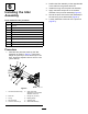
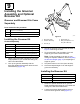
Form No. 3421-332 Rev C Universal Groomer Drive MVP Kit Reelmaster® 18-inch, 22-inch, or 27-inch Cutting Units with 5-inch or 7-inch Reel Model No. 133-0150 Model No. 133-0151 Installation Instructions Loose Parts Use the chart below to verify that all parts have been shipped. Procedure 1 2 3 4 5 6 7 8 © 2019—The Toro® Company 8111 Lyndale Avenue South Bloomington, MN 55420 Description Qty. Use No parts required – Prepare the machine. No parts required – Gather the tools required for setup.
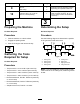
Procedure 9 10 Description Use Qty. Bolt (1/4 x 1-1/2 inches) Jam nut Shaft clamp Hydraulic fitting—45° (Part No. 340–101; sold separately) 1 4 4 4 Install the groomer assembly (ordered separately) and optional broomer kit. 1 Install the angled fitting (for Reelmaster 3550 and 3555 machines, #1 front, center cutting location and kit Model 133-0150). 3 Preparing the Machine Determining the Setup No Parts Required No Parts Required Procedure Procedure 1. Park the machine on a level surface.
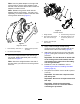
tool (Part No. TOR4112 for the 5-inch reel and Part No. TOR4074 for the 7-inch reel). Refer to Figure 3. 4 Important: The splined insert on the left Preparing the Cutting Unit side of the cutting unit has left-hand threads. The splined insert on the right side of the cutting unit has right-hand threads.
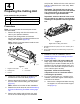
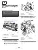
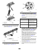
5 Installing the Weight Bracket and the Groomer Drive Box Parts needed for this procedure: 1 Weight bracket 2 Hex-socket, button-head bolt (3/8 x 3/4 inch) 1 Right (yellow) reel adapter 1 Left (green) reel adapter 1 Groomer drive box g037064 Figure 4 1. Flange-head bolts B. 2. Support rod Install the 2 existing flange-head bolts from the inside of the cutting unit, and secure them with the 3/8 inch flange locknuts (Figure 5). Procedure 1.
Note: Use the yellow adapter on the right side of the machine; use the green adapter on the left side of the machine. Discard the unused reel adapter included in the kit. Note: Restrain the groomer shaft with the adapter wrench tool (Part No. 137-0921, sold separately) on the wrench flats on the back side of the groomer drive box (Figure 7). g227902 Figure 8 Left side shown 1. Weight bracket 4. Thread-locking compound 2. Hex-socket, button-head bolt—3/8 x 3/4 inch (2) 5.
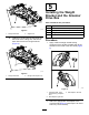
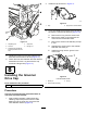
Installing the Idler Assembly Parts needed for this procedure: 2 Hex-socket-head bolt 1 Pivot hub 1 O-ring 1 Idler assembly 2 Bearing shield 1 Adjuster collar 1 Stub-shaft assembly 1 Flange nut (3/4 inch) 2 Flange locknut (3/8 inch)—Model 133-0150 only 2 Jam locknut (3/8 inch)—Model 133-0151 only Procedure 1. Assemble the parts that make up the idler assembly as shown in Figure 9.
Installing the HOC Bracket Assemblies and the Front Roller Parts needed for this procedure: 1 Left HOC bracket assembly 1 Right HOC bracket assembly 2 Adjuster pin 1. Adjuster pin 3. Cotter pin 2 Cotter pin 2. Adjuster-arm rod 4. Groomer drive box 2 Flange locknut (3/8 with 5/8 hex) g232400 Figure 11 3. Procedure 1.
2. Install the cap as shown in Figure 14. g242099 Figure 14 1. Cap 3. 2. Apply Green Loctite 609® If you are installing the groomer at the left side of the machine, perform the following (Figure 15): A. Remove the O-ring from the clutch knob. B. Remove the shear pin that secures the clutch knob to the actuator shaft. C. Remove the clutch-knob assembly and flip it over. D. Assemble the clutch knob to the actuator shaft with the shear pin. E.
Installing the Groomer Assembly and Optional Broomer Kit Groomer and Broomer Kits Come Separately Parts needed for this procedure: 4 Bolt (1/4 x 1-1/2 inches) 4 Jam nut 4 Shaft clamp g240752 Figure 16 Installing the Groomer Kit Ordered Separately Model Number 18 inch Groomer Blade Cartridge Kit 03772 22 inch Groomer Blade Cartridge Kit 03778 27-inch Groomer Blade Cartridge Kit 03766 18 inch Fairway QC Grooming Brush Kit 03767 22 inch Fairway QC Grooming Brush Kit 1.
g032402 Figure 19 1. Brush 5. 2. Blade Loosely wrap the straps, as shown in Figure 17, around the groomer reel shaft and brushes, inserting the straps in the grooves in the brushes Figure 19.
10 Installing the Angled Fitting For Reelmaster 3550 and 3555 Machines—#1 Front, Center Cutting Location and Kit Model 133-0150 Only Parts needed for this procedure: 1 Hydraulic fitting—45° (Part No. 340–101; sold separately) Procedure Important: For Reelmaster 3550 and 3555 machines—#1 front, center cutting location and kit model 133-0150 only; order 45° hydraulic fitting (Part No. 340–101) and follow the procedure below. 1. Remove the hydraulic hose from the hydraulic fitting on the motor. 2.
Operation • The type of grass • The overall management program (i.e., irrigation, fertilizing, spraying, coring, overseeding, etc.) Introduction • Traffic Grooming is performed in the turf canopy above the soil level. Grooming promotes vertical growth of grass plants, reduces grain, and severs stolons, producing a denser turf. Grooming produces a more uniform and tighter playing surface for faster and truer action of the golf ball. • Stress periods (i.e.
Adjusting the Groomer Height 5. The height setting on both ends of the groomer should be identical. Adjust the height as required. DANGER Contact with the reels or other moving parts can result in personal injury. • Before making any adjustments to the cutting units, disengage the reels, set the parking brake, shut off the engine, and remove the key. • Keep your hands and clothing away from the reels or other moving parts. 1.
Height-of-Cut (HOC) and Height-of-Groom (HOG) Recommended Range Height-of-Cut (mm) Height-of-Cut (inch) Number of Rear Roller Spacers Recommended HOG = HOC Groomer Engagement Recommended HOG = HOC Groomer Engagement (mm) (inch) 6.3 0.250 0 3.1 to 6.3 0.125 to 0.250 9.5 0.375 0 4.7 to 9.5 0.187 to 0.375 9.5 0.375 1 4.7 to 9.5 0.187 to 0.375 12.7 0.500 0 6.3 to 12.7 0.250 to 0.500 12.7 0.500 1 6.3 to 12.7 0.250 to 0.500 12.7 0.500 2 6.3 to 9.5 0.250 to 0.375 15.8 0.
Maintenance Testing the Groomer Performance DANGER Important: Improper or over-aggressive use of Contact with the reels or other moving parts can result in personal injury. the grooming reel (i.e., too deep or too frequent grooming) may cause unnecessary stress on the turf, leading to severe damage. Use the groomer cautiously. • Before making any adjustments to the cutting units, disengage the reels, set the parking brake, shut off the engine, and remove the key.
g241100 Figure 26 Right side groomer box shown g240875 Figure 24 1. Remove the drain plug from the drain port. 3. Loosen the air-vent plug. 1. Air-vent plug 3. Drain plug 2. Fill plug 2. Remove the fill plug from the fill port. 6. Rock the cutting unit back and forth to ensure complete drainage. When the oil is completely drained, place the cutting unit on a level surface. Removing the Groomer Drive Box 7. Install the drain plug. Note: Retain all removed parts for later installation 8.
Cleaning the Grooming Reel Service Interval: After each use Clean off the grooming reel after using it by spraying it with water. Do not direct the water stream directly at the groomer bearing seals. Do not permit the grooming reel to stand in water so that the components rust. Inspecting the Blades Service Interval: Before each use or daily Inspect the grooming-reel blades frequently for damage and wear. Straighten bent blades with a pliers and replace worn blades.
Restraining the Reel WARNING The cutting reel blades are sharp and capable of amputating hands and feet. • Keep your hands and feet outside of the reel. • Ensure that the reel is restrained before servicing it. Restraining the Reel for Removing Threaded Inserts 1. 2. 3. Loosen the shield-bolt on the left side of the cutting unit and raise the rear shield (Figure 29).
Restraining the Reel for Installing Threaded Inserts 1. Insert a long-handled pry bar (recommended 3/8" x 12" with screwdriver handle) through the front of the cutting reel, closest to the side of the cutting unit that you will be torquing (Figure 30). 2. Place the pry bar against the weld side of the internal cutting reel reinforcement (Figure 30). Note: The pry bar should contact a blade at the front, the reel shaft, and a blade at the back of the back of the reel, locking it in place.
Declaration of Incorporation The Toro Company, 8111 Lyndale Ave. South, Bloomington, MN, USA declares that the following unit(s) conform(s) to the directives listed, when installed in accordance with the accompanying instructions onto certain Toro models as indicated on the relevant Declarations of Conformity. Model No. Serial No.