Form No. 3408-241 Rev A Field Kit 2024 Directional Drill Model No. 133-9467 Installation Instructions WARNING CALIFORNIA Proposition 65 Warning This product contains a chemical or chemicals known to the State of California to cause cancer, birth defects, or reproductive harm. Safety Safety and Instructional Decals Safety decals and instructions are easily visible to the operator and are located near any area of potential danger. Replace any decal that is damaged or missing.
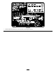
125-6189 1. Read the Operator's Manual for more information on servicing the machine.
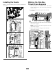
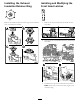
Installing the Decals Welding the Rod-Box Thrust-Frame Supports Remove the current decal, clean the surface, and install the new decals. 1. Park the machine on a hard level surface. Shut off the engine, remove the key, and set the battery disconnect switch to OFF. 2. Locate the thrust-frame supports near the cam assemblies. 3. Remove all of the paint and dirt on the front and rear thrust-frame supports. Note: Protect the hoses and wiring harness near the thrust-frame supports. 4.
Rear thrust-frame support (horizontal weld) Rear thrust-frame support (vertical weld) 5. Inspect the vertical weld on the front and rear thrust-frame supports. If the weld shows signs of fatigue, repeat step 3 and weld this area. 6. After the welds cool, prime and paint the welded areas with semi-gloss black paint.
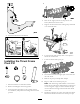
Installing the Exhaust Insulation Retainer Ring Installing and Modifying the Front Hood Latches Remove the insulation, fold the retainer ring on the insulation piece, and install the assembly. 1. Remove the current hood latch and install the new hood latch. 2. Open the front hood and disconnect the internal front hood latch. 3. Grind down the tip of the internal front hood latch. Note: Ensure that you leave the hook length 1.6 cm (0.63 inch) long.
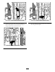
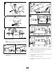
4. Shut off the engine, remove the key, and set the battery-disconnect switch to OFF. 5. Support the thrust frame with a lifting strap connected to an overhead crane. 4. Install the internal front hood latch. 6. Loosen the left track tension; refer to the Operator’s Manual for the machine. 7. Locate the thrust frame pivot pin. Installing the Thrust Frame Pivot Pin 8. Insert blocks between the upper part of the track and the track frame. 9. Remove the pivot pin keeper bolt and pin. 10.
12. Replace the bushing. Note: If the bushing is welded in place, grind the weld smooth before installing the new pin. 14. Remove the temporary pin and replace the bushing. Note: If the bushing is welded in place, grind the weld smooth before installing the new pin. 15. Push the new pin all the way in. 16. Using the pivot flag pin as a guide, drill a hole into the thrust frame. 13. Add grease to the new pivot pin and push it in almost all the way in. 17. Install the bolt, washer, and nut. 18.
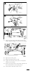
19. Clean the grease fittings and pump grease into the fittings until grease beigns to ooze out of the bearings. 20. Wipe up any excess grease. 21. Remove the blocks from the track. 22. Tighten the left track tension; refer to the Operator’s Manual for the machine. 23. Remove the strap from the thrust frame and lower the thrust frame back into the stowed position. 24. Set the battery disconnect switch to ON.