
Installation Instructions

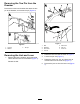
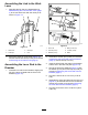


AssemblingtheLinktotheHitch
Lever
1.Assemblethelinkthatyoudisassembledin
DisassemblingtheLinkandHitchLever(page
4)tothenewhitchleverwiththeclevispinas
showninFigure12.
g287828
Figure12
1.Hitchlever
3.Clevispin
2.Cotterpin
4.Link
2.Securetheclevispintothelever(Figure12)
withthewasherandcotterpinthatyouremoved
inRemovingtheLinkandLever(page3).
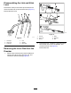
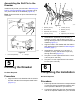
AssemblingtheLeverRodtothe
Drawbar
1.Inserttheleverrodintothedrawbar,aligningthe
slotinthelever-rodplatewiththeholeinthe
drawbar(Figure12).
g287831
Figure13
1.Leverrod
4.Bolt(8x65mm)
2.Locknut(8mm)5.Locknut(6mm)
3.Washer(8mm)6.Slide
2.Assembleawasher(8mm)thatyouremoved
inRemovingtheLeverRodfromtheDrawbar
(page4)ontothebolt(8x65mm).
3.Inserttheboltthroughtheholesinthedrawbar
andtheslotinthelever-rodplate(Figure13).
4.Securethebolttothedrawbar(Figure13)with
thewasher(8mm)andlocknut(8mm)thatyou
removedinRemovingtheLeverRodfromthe
Drawbar(page4).
5.Torquethelocknutto47to57N∙m(34to42
ft-lb).
6.Assemblethespringandslideovertheleverrod
(Figure13)andsecurethemtotherodwiththe
locknut(6mm)thatyouremovedinRemoving
theLeverRodfromtheDrawbar(page4).
7.Torquethelocknutto972to1198N∙cm(86to
106in-lb).
6