
Installation Instructions

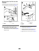


AssemblingtheHitchLevertothe
Drawbar
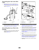
1.Threadthejamnutontotheleverrod(Figure
14).
g287895
Figure14
1.Clevisfork
5.Washers
2.Jamnut6.Hitchlever
3.Leverrod
7.Bracket(drawbar)
4.Bolt(8x75mm)
8.Locknut
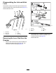
2.Threadtheclevisfork,link,andhitchleveronto
theleverrod(Figure14).
3.Aligntheholesinthehitchleverwiththeholes
inthedrawbarbracket(Figure14).
4.Assemblethehitchlevertothebracket(Figure
14)withthewashersandlocknutthatyou
removedinRemovingtheLinkandLever(page
3)andthebolt(8x75mm).
5.Tightenthelocknutandboltuntilyouremove
theendplay(Figure14).
6.Tightenjamnut(Figure14).
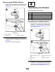
AssemblingtheHitchPintothe
Drawbar
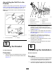
1.Rotatethehitchleveruptoretracttheslide,and
securethelever(Figure15).
g287896
Figure15
1.Hitchpin
3.Washer(16mm)
2.Locknut(16mm)4.Uppertab(drawbar)
2.AlignthehitchpinthatyouremovedinRemoving
theT owPinfromtheDrawbar(page3)withthe
taperedseatup.
3.Insertthehitchpinintotheholeinthelowertab
ofthedrawbar(Figure15).
4.Insertthehitchpinthroughtheholeintheupper
tabofthedrawbaruntilthetaperedseatushin
theuppertab(Figure15).
5.Securethehitchpintotheuppertabwiththe
washer(16mm)andlocknut(16mm)thatyou
removedinRemovingtheTowPinfromthe
Drawbar(page3).
6.Torquethelocknutto204to247N∙m(149to
183ft-lb).
7