
Installation Instructions

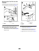


AssemblingtheRollPintothe
Drawbar
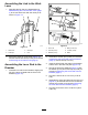
InstalltherollpinthatyouremovedinRemovingthe
RollPinfromtheDrawbar(page2)intothehole(8
mm)inthelowertabofthedrawbar(Figure16).
Note:Ensurethattherollpinisushwiththetop
ofthetab.
g287897
Figure16
1.Lowertab(drawbar)
2.Rollpin
5
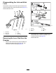
InstallingtheDrawbar
NoPartsRequired
Procedure
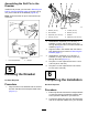
1.Aligntheholesinthedrawbarwiththeholesin
thehitchbracketofthetransport-wheelframe
(Figure17).
g287898
Figure17
1.Washer(10mm)5.Locknut(12mm)
2.Hitchbracket
6.Washer(12mm)
3.Capscrew(10x100mm)
7.Drawbar
4.Locknut(10mm)8.Capscrew(12x100mm)
2.Assemblethecapscrew(12x100mm),2
washers(12mm),andthelocknut(12mm)
throughthelargerholesinthehitchbracketand
drawbar(Figure17).
3.Aligntheholesinthedrawbarwiththeholesin
hitchbracketthatyounotedin2Removingthe
Drawbar(page1).
4.Assemblethecapscrew(10x100mm),2
washers(10mm),andthelocknut(10mm)
throughtheholes(Figure17).
5.Torquethe12mmcapscrewandnutto112to
140N∙m(83to103ft-lb).
6.Torquethe10mmcapscrewandnutto65to
81N∙m(48to160ft-lb).
6
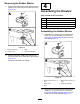
CompletingtheInstallation
NoPartsRequired
Procedure
1.Eitherfullyraiseandsecurethetransportwheels
orlowerandsecurethetransportwheels;refer
totheOperator’sManualforyourmachine.
2.Connectthespark-plugwirefromthesparkplug;
refertotheOperator’sManualforyourmachine.
8