
Installation Instructions
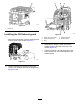


2.Removethescrew(5/16x3/4inch)thatsecures
thebushingtothetransmissionhousing,and
removethebushing(Figure26).
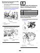
g289451
Figure26
1.Screw(5/16x1inch)
5.Bushing
2.Lowerbidirectionalarm6.Washer
3.Upperbidirectionalarm
7.Spring
4.Screw(5/16x3/4inch)
8.Return-controlarm
3.Removethespringfromtheupperandlower
bidirectionalarms(Figure26).
4.Removethescrew(5/16x1inch)thatsecures
theupperandlowerbidirectionalarms,and
return-controlarmtothetransmissionhousing,
andremovethearms(Figure26).
Note:Discardtheupperandlowerbidirectional
arms.
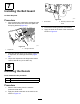
InstallingtheUpperandLower
ReturnArmandtheNeutralArm
1.Assembletheupperreturnarm,lowerreturn
arm,return-controlarm,andneutralarmand
reverseswitchtothetransmissionhousingwith
thetorx-headscrewasshowninFigure27.
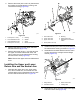
g289442
Figure27
1.Torx-headscrew5.Bushing
2.Lowerreturnarm6.Return-controlarm
3.Upperreturnarm7.Neutralarmandreverse
switch
4.Screw(5/16x3/4inch)
2.Installthescrew(5/16x3/4inch)andbushingto
thetransmissionhousingasshowninFigure27.
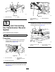
3.Assemblethetransaxlebracketontothereturn
controlarmwiththecarriageboltandange
locknut(Figure28).
g289444
Figure28
1.Flangelocknut3.Returncontrolarm
2.Transaxlebracket
4.Carriagebolt
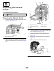
4.Assemblethespringontothehooksoftheupper
andlowerreturnarms(Figure29).
12