
Installation Instructions
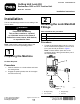

2.Threadthestraightttingintothe2portonthe
lockmanifoldandtightenitto24.4to29.8N·m
(18to22ft-lb)asshowninFigure1.
3
InstallingtheCuttingUnit
LockManifold
Partsneededforthisprocedure:
1
Lockmanifold
1
Lock-manifoldbracket
1Kitwireharness
1Kithose
Procedure
1.Disconnectthebattery;refertoyourOperator’s
Manual.
Note:Youmaywanttojackupthemachineor
useahoisttoaccessthemanifoldmoreeasily.
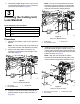
2.Removetheangeboltssecuringthelift
manifoldtothebracketonthetoprightofthe
frontaxle(Figure2).
g213740
Figure2
RearofLiftManifoldShown
1.Liftmanifold
3.Flangebolts
2.Lift-manifoldbracket
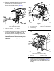
3.Installthelock-manifoldbracketbeneaththe
existingbracketusingtheboltsremovedin2.
(Figure3).
Note:Thenotchinthebracketshouldpoint
towardtherightofthemachine,andthewider
endshouldpointedtowardtherearendofthe
machine,ushwiththeexistingbracket.
g213741
Figure3
RearofLiftManifoldShown
1.Liftmanifold
3.Flangenuts
2.Lock-manifoldbracket
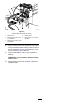
4.Installthelockmanifoldtothebottomofthe
manifoldbracketusingthe2bolts(1/4by1-3/4
inches)and2locknuts(3/8inches)withthebolt
enteringthetopofthebracketandthenutatthe
bottomasshowninFigure4.
Note:Alignthelockmanifoldsothatthe
solenoidispointedtowardtherightsideofthe
machineandthettingspointtowardthefront.
g213742
Figure4
Hosesnotshownforclarity
1.Bolts(1/4by1-3/4inches)3.Locknuts(3/8inches)
2.Lockmanifold
2