
Installation Instructions


g009080
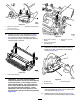
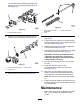
Figure30
1.Sideplate
4.Rearroller
2.Rollerbrush5.Ensurethatthereis
clearancehere.
3.Lightcontact
Note:Therollerbrushshaftmustbeparallel
totherearroller.
Note:Theorientationofthenon–driveroller
brushbearinghousingshouldbethesameas
drivesidebearinghousing.
18.Tightenthe2boltssecuringeachrollerbrush
bearinghousingtotherollerbrushmounting
brackets.
19.Apply243Loctite(blue)totheshoulderbolt
(Figure27).Securethebrushplatetothe
groomercoverwiththeshoulderbolt.(Figure
27).T orquetheboltto20to25N∙m(15to19
ft-lb).
Note:Theshoulderboltshouldnotclampthe
platetothehousing.
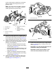
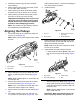
20.Removetheboltsecuringthegroomerpulleyto
thedriveshaft(Figure31).
21.Insertthebrushdrivepulleyintothegroomer
drivepulleyandontothedriveshaft(Figure31).
Makesurethatthepulleytabsarepositionedin
theslotinthedriveshaft.
22.Securethedrivepulleytotheshaftwitha
ange-headbolt(3/8x2inch)(Figure31).
Torquetheboltto47to54N∙m(35to40ft-lb).
Important:Iftheboltisnotproperly
torqued,theboltwillcomeloose.
Restrainthereelforinstallation;referto
RestrainingtheReelforInstallingThreaded
Inserts(page18).
g009069
Figure31
1.Groomerpulleymounting
bolt(remove)
3.Bolt-Torqueto47to54
N∙m(35to40ft-lb)
2.Drivepulley
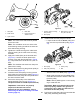
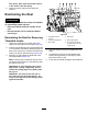
23.Installthebeltontothepulleysasfollows:
•Loopthebeltaroundthedrivenpulleyand
thenoverthetopoftheidlerpulley(Figure
32).
g009070
Figure32
1.Drivepulley3.Drivenpulley
2.Idlerpulleyassembly4.Belt
•Startthebeltonthedrivepulley(Figure32).
•Whileguidingthebeltontothedrivepulley,
rotatethereelforwardtodrawthebeltonto
thedrivepulley.
Note:Wearapaddedgloveoruseaheavy
ragtorotatethereel.
Important:Makesurethattheribsonthe
beltareproperlyseatedinthegroovesin
eachpulley.Also,makesurethebeltisin
thecenteroftheidlerpulley.
24.Pushdownontheidlerpulleytoensurethatthe
idlerpulleyassemblypivotsfreely.
13