
Installation Instructions


2.Greasethettingsevery50hoursandafter
everywashing.
3.Whenreplacingrollerbrush,torquetheJ-bolts
to2to3N∙m(20to25in-lb).
4.Whenreplacingthebrush-shaft-drivenpulley,
torquethenutto36to45N∙m(27to33ft-lb).
5.Whenreplacingthebrush-drivepulley,torque
theboltto47to54N∙m(35to40ft-lb).
Important:Backlappingattheincorrectreel
speedmayloosenandstripthedrive-pulley
threads.Refertothecuttingunitoperator’s
manualforthebacklappingprocedure.
Note:Therollerbrush,idlerbearing,andbelt
areconsideredconsumableitems.
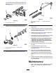
AligningthePulleys
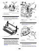
1.Thedrivenpulley(attheroller-brushshaft)can
moveinorout(Figure39).
Note:Makenoteofwhichwaythepulleyneeds
tomove.
g009076
Figure39
1.Drivenpulley3.Driven-pulleynut
2.Idlerpulley
2.Whilerotatingthereel,whichrotatesthedrive
pulley,prythebeltoffthedrivepulley(Figure
39).
Note:Wearapaddedgloveoruseaheavyrag
torotatethereel.
3.Removethelocknutsecuringthedrivenpulley
tothebrushshaft(Figure39orFigure40).
Note:Puta1/2-inchwrenchontheatsofthe
roller-brushshafttokeepitfromrotating.
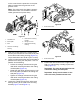
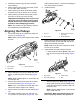
4.Removethedrivenpulleyfromtheshaft(Figure
40).
5.Ifthepulleyneedstomoveout,addone0.8
mm(0.032inch)thickspacer(Figure40).Ifthe
pulleyneedstomovein,removetheexisting0.8
mm(0.032inch)thickspacer.
6.Installthepulley.
g009077
Figure40
1.Locknut
3.Spacer(0.032inch(0.8
mm)thick)
2.Drivenpulley
4.Brush-shaftats
7.Whileholdingtheatsoftheroller-brushshaft,
securethepulleyontheshaftwiththe3/8-16
angenutpreviouslyremoved.
Note:Seatthelocknut,thentorqueitto36to
45N∙m(27to33ft-lb).
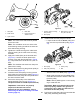
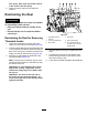
8.Installthebeltontothepulleysasfollows:
•Loopthebeltaroundthedrivenpulleyand
thenoverthetopoftheidlerpulley(Figure
41).
g009059
Figure41
1.Drivepulley3.Drivenpulley
2.Idler-pulleyassembly4.Belt
•Startthebeltonthedrivepulley(Figure41).
•Whileguidingthebeltontothedrivepulley,
rotatethereelforwardtodrawthebeltonto
thedrivepulley.
Note:Wearapaddedgloveoruseaheavy
ragtorotatethereel.
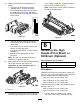
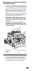
Important:Makesurethattheribsonthe
beltareproperlyseatedinthegroovesin
16