
Installation Instructions
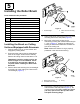

5
InstallingtheRollerBrush
Partsneededforthisprocedure:
1Roller-brushhousing
2
Allen-headbolt,3/8x1inch
1Roller-brushassembly
1
Shoulderbolt
1
Beltcover/plateassembly
2
Bolt,5/16x5/8inch
1
Spacer
1Drivepulley
1
Flange-headbolt,3/8x2inches
1Belt
1
Shimwasher(asrequired)
InstallingtheBrushonCutting
UnitsnotEquippedwithGroomers
1.Parkthetractionunitonalevelsurfaceand
engagetheparkingbrake.
2.Ensurethatthecuttingunitsaredisengaged.
Shutofftheengineoffandremovethekey.
Removeallcuttingunitsfromthetractionunit.
Important:Checkthecuttingunitforthe
desiredheightofcutandattitude.Reset
itaccordingtotheOperator’sManual,if
required,beforeinstallingtheRearRoller
BrushKit.
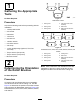
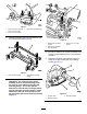
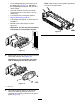
3.Removethe2boltssecuringthecounterweight
totheleftendofthecuttingunit.Removethe
counterweight(Figure5).
g009050
Figure5
1.Counterweight2.Cleanoutthesemounting
holes.
4.Usinga3/8-16tap,removethepaintintheouter
mountingholesintheside-plate(Figure5).
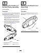
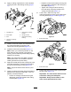
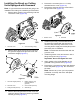
5.Mounttheroller-brushhousingtothe
reel-bearinghousingwith2Allen-headbolts(3/8
x1inch)(Figure6).Positiontheroller-brush
housingsothatthethreadedholeistowardthe
frontofthecuttingunit.
Note:MakesurethattheO-ringisproperly
positionedintheroller-brushhousing.
g009052
Figure6
1.Roller-brushhousing
3.O-ring
2.Threadedholeinhousing
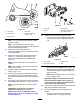
6.Removethe2angelocknutssecuringeach
rollerbrackettotheside-plates(Figure7).Do
notremovethebolts.Also,removeany6mm
(1/4inch)spacersfromthetopsideofthe
side-platemountingange.
5